background image

OPERATION 

31

Using Your Garage Door Opener

Your Security

®

opener and hand-held remote

control have been factory-set to a matching code
which changes with each use, randomly accessing
over 100 billion new codes. Your opener will operate
with up to eight Security

®

remote controls and one

Security

®

Keyless Entry System. If you purchase a

new remote, or if you wish to deactivate any remote,
follow the instructions in the 

Programming

section. 

Activate your opener with any of the following:

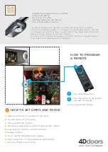
The hand-held Remote Control:

Hold the push

button down until the door starts to move.

The wall-mounted Door Control:

Hold the push

button or bar down until the door starts to move.

The Keyless Entry (See Accessories):

If supplied

with your garage door opener, it must be
programmed before use. See 

Programming.

When the opener is activated (with the safety
reversing sensor correctly installed and aligned)

1. If open, the door will close. If closed, it will open.
2. If closing, the door will reverse.
3. If opening, the door will stop.

4. If the door has been stopped in a partially open

position, it will close.

5. If obstructed while closing, the door will reverse. If

the obstruction interrupts the sensor beam, the
opener lights will blink for five seconds.

6. If obstructed while opening, the door will stop.
7. If fully open, the door will not close when the beam

is broken. The sensor has no effect in the opening
cycle.

If the sensor is not installed, or is misaligned, the
door won't close from a hand-held remote. However,
you can close the door with the Door Control, the
Outside Keylock, or Keyless Entry, 

if you activate

them until down travel is complete. 

If you release

them too soon, the door will reverse. 

The opener light

will turn on under the following

conditions: when the opener is initially plugged in;
when power is restored after interruption; when the
opener is activated. 
The light will also turn on when someone walks
through the open garage door. 
It will turn off automatically after 4-1/2 minutes. Bulb
size is 75 watts maximum.

IMPORTANT SAFETY INSTRUCTIONS

To reduce the risk of SEVERE INJURY or DEATH:

WARNING

WARNING

WARNING

1. READ AND FOLLOW ALL WARNINGS AND

INSTRUCTIONS.

2. ALWAYS keep remote controls out of reach of children.

NEVER permit children to operate or play with garage
door control push buttons or remote controls. 

3. ONLY activate garage door when it can be seen clearly, it

is properly adjusted, and there are no obstructions to
door travel.

4. ALWAYS keep garage door in sight until completely

closed. NO ONE SHOULD CROSS THE PATH OF THE
MOVING DOOR.

5. NO ONE SHOULD GO UNDER A STOPPED, PARTIALLY

OPEN DOOR.

6. If possible, use emergency release handle to disengage

trolley ONLY when garage door is CLOSED. Weak or
broken springs or unbalanced door could result in an
open door falling rapidly and/or unexpectedly.

7. NEVER use emergency release handle unless garage

doorway is clear of persons and obstructions.

8. NEVER use handle to pull garage door open or closed. If

rope knot becomes untied, you could fall.

9. If one control (force or travel limits) is adjusted, the

other control may also need adjustment.

10. After ANY adjustments are made, the safety reversal

system MUST be tested.

11. Safety reversal system MUST be tested every month.

Garage door MUST reverse on contact with 1-1/2" 
(3.8 cm) high object (or a 2 x 4 laid flat) on the floor.

12. ALWAYS KEEP GARAGE DOOR PROPERLY BALANCED

(see page 3). An improperly balanced door may not
reverse when required and could result in SEVERE
INJURY or DEATH.

13. All repairs to cables, spring assemblies and other

hardware, all of which are under EXTREME tension,
MUST be made by a trained door systems technician.

14. ALWAYS disconnect electric power to garage door

opener BEFORE making any repairs or removing
covers.

15.

SAVE THESE INSTRUCTIONS.

Summary of Contents for Lift-Master 1240R - 1/4HP

Page 1: ...losed safety materials carefully Fasten the manual near the garage door after installation The door WILL NOT CLOSE unless the Protector System is connected and properly aligned Periodic checks of the...

Page 2: ...8 11 Fasten the rail to the motor unit 8 9 Install the chain and the sprocket cover 8 Install the chain spreader and the chain 10 Tighten the chain 11 Installation 11 27 Installation safety instructi...

Page 3: ...your garage door Before you begin Disable locks Remove any ropes connected to garage door Complete the following test to make sure your garage door is balanced and is not sticking or binding 1 Lift t...

Page 4: ...ling in your garage If so a support bracket and additional fastening hardware may be required Installation Step 10 Depending upon garage construction extension brackets or wood blocks may be needed to...

Page 5: ...Header Wall Planning Continued ONE PIECE DOOR INSTALLATIONS Generally a one piece door does not require reinforcement If your door is lightweight refer to the information relating to sectional doors i...

Page 6: ...46R Trolley Chain Door Bracket SECURITY Single Button Remote Control 1 2 Safety Reversing Sensors 1 Sending Eye and 1 Receiving Eye with 2 Conductor White White Black Bell Wire attached Safety Sensor...

Page 7: ...in 5 16 x2 3 4 1 NOTICE Handle Dry Wall Anchors 2 Clevis Pin 5 16 x1 1 Clevis Pin 5 16 x1 1 4 1 Hex Bolt 5 16 18x7 8 4 Rope Ring Fastener 3 Lock Washer 5 16 4 Lag Screw 5 16 9 x1 5 8 2 Wing Nut 1 4 20...

Page 8: ...REMOVE STYROFOAM Washered Bolt 5 16 18x1 2 Styrofoam Rail Hole USE ONLY THIS TYPE AND SIZE BOLT Washered Bolt 5 16 18x1 2 Motor Unit Sprocket USE ONLY THIS TYPE AND SIZE BOLT Sprocket Cover Mounting P...

Page 9: ...n the rail with the two washered bolts previously removed Tighten securely Use only these bolts Use of any other bolts will cause serious damage to door opener USE ONLY THIS TYPE AND SIZE BOLT Washere...

Page 10: ...own Figure 3 Continue dispensing the chain forward to the trolley Figure 4 Reconnect the trolley to the trolley threaded shaft Proceed to Assembly Step 3 for chain tightening instructions Trolley Trol...

Page 11: ...ll garage door opener only on properly balanced and lubricated garage door An improperly balanced door may not reverse when required and could result in SEVERE INJURY or DEATH 3 All repairs to cables...

Page 12: ...shown Draw an intersecting horizontal line on the header wall 2 5 cm above the high point This height will provide travel clearance for the top edge of the door Proceed to Step 2 page 14 One piece do...

Page 13: ...om the top of the door to the floor Subtract the actual height of the door Add 8 20 cm to the remainder See Example 3 Close the door and draw an intersecting horizontal line on the header wall at the...

Page 14: ...P CEILING MOUNT ONLY Wall Mounting Holes Optional Wall Mounting Holes The nail hole is for positioning only You must use lag screws to mount the header bracket UP CEILING MOUNT ONLY Door Spring Header...

Page 15: ...ou ll need help Have someone hold the opener securely on a temporary support to allow the rail to clear the spring Position the rail bracket against the header bracket Align the bracket holes and join...

Page 16: ...ent for setting an ideal door to rail distance Raise the opener onto a stepladder You will need help at this point if the ladder is not tall enough Open the door all the way and place a 2x4 laid flat...

Page 17: ...the rail is centered over the door or in line with the header bracket if the bracket is not centered above the door 7 Remove the 2x4 Operate the door manually If the door hits the rail raise the head...

Page 18: ...two screw terminals on the back of the door control by color white wire to 2 and white red wire to 1 2 Fasten the Lighted Door Control Button securely with 6ABx1 1 2 screws If installing into drywall...

Page 19: ...Secure with an overhand knot at least 1 2 5 mm from the end of the rope to prevent slipping Thread the other end of the rope through the hole in the release arm of the outer trolley Adjust rope length...

Page 20: ...he black line wire to the screw on the brass terminal the white neutral wire to the screw on the silver terminal and the ground wire to the green ground screw The opener must be grounded Reinstall the...

Page 21: ...r Either can be installed on the left or right of the door as long as the sun never shines directly into the receiving eye lens The mounting brackets are designed to clip onto the track of sectional g...

Page 22: ...p hugging the back edge of the track as shown in Figure 1 If your door track will not support the bracket securely wall installation is recommended Wall installation Figure 2 3 Place the bracket again...

Page 23: ...the sending eye wing nut and readjust aiming directly at the receiving eye Lock in place Loosen the receiving eye wing nut and adjust sensor until it receives the sender s beam When the green indicat...

Page 24: ...racket Drill 3 16 fastening holes Secure the door bracket using the two 1 4 14x5 8 self threading screws Figure 2A Alternately use two 5 16 bolts lock washers and nuts not provided Figure 2B Metal ins...

Page 25: ...INUM STEEL DOORS WITH GLASS PANEL ETC NOT PROVIDED ONE PIECE DOORS Please read and comply with the warnings and reinforcement instructions on the previous page They apply to one piece doors also Cente...

Page 26: ...as far apart as possible to increase door arm rigidity Figure 3 Hole alignment alternative If holes in curved arm are above holes in straight arm disconnect straight arm Cut about 6 from the solid end...

Page 27: ...s 5 16 Ring Fastener Straight Arm Bolts 5 16 18x7 8 Door Bracket Clevis Pin 5 16 x1 1 4 Curved Door Arm Press the Door Control push button The trolley will travel to the fully closed position Manually...

Page 28: ...ined in Adjustment Step 2 If the door does not close completely Increase down travel Turn the down limit adjustment screw counterclockwise One turn equals 2 5 cm of travel If door still won t close co...

Page 29: ...clockwise Make small adjustments until the door completes a close cycle After each adjustment run the opener through a complete travel cycle Do not increase the force beyond the minimum amount requir...

Page 30: ...the 1 1 2 3 8 cm board remove the obstruction and run the opener through 3 or 4 complete travel cycles to test adjustment IMPORTANT SAFETY CHECK Repeat Adjustment Steps 1 2 and 3 after Each adjustment...

Page 31: ...n power is restored after interruption when the opener is activated The light will also turn on when someone walks through the open garage door It will turn off automatically after 4 1 2 minutes Bulb...

Page 32: ...ess the push button to open or close the door Press again to reverse the door during the closing cycle or to stop the door while it s opening To prevent possible SERIOUS INJURY or DEATH from a falling...

Page 33: ...ol Is the door control lit If not remove the bell wire from the motor unit terminals Short the red and white terminals by touching both terminals at the same time with a piece of wire If the opener ru...

Page 34: ...adjustments to force or travel limits The need for occasional adjustment of the force and limit settings is normal Weather conditions in particular can affect door travel 11 The door reverses for no...

Page 35: ...5 1 2 3 1 2 1 Press and release the learn button on the motor unit The learn indicator light will glow steadily for 30 seconds 2 Within 30 seconds press and hold the button on the hand held remote tha...

Page 36: ...s for the present PIN then press and hold the button The opener light will blink twice Release the button 2 Press the new 4 digit PIN you have chosen then press Enter The motor unit lights will blink...

Page 37: ...8 41A5047 Door bracket w clevis pin fastener 9 41A5034 Safety sensor kit receiving and sending eyes with 3 9 m 2 conductor bell wire attached 10 178B34 Straight door arm section 11 178B35 Curved door...

Page 38: ...s 6 175B88 Light socket 7 108D36 Lens All models except 1240R 8 30B363 Capacitor 1 2HP 30B387 Capacitor 1 3HP 30B366 Capacitor 1 4HP 9 12A373 Capacitor bracket 10 41A3150 Terminal block w screws KEY P...

Page 39: ...y entering a password on a specially designed keyboard Also can add a temporary password for visitors or service persons This temporary password can be limited to a programmable number of hours or ent...

Page 40: ...pon receipt by Seller are confirmed to be defective and covered by this limited warranty will be repaired or replaced at Seller s sole option at no cost to you and returned pre paid Defective parts wi...

Reviews: