F U L L I N S TA L L AT I O N M A N U A L C A N B E D O W N L O A D E D
AT
L I F T M A S T E R . C O M / C A P 2 D
.
G O T O
AC C E S S . L I F T M A S T E RT R A I N I N G. C O M
F O R
A D D I T I O N A L I N S T R U C T I O N S I N C L U D I N G F U L L M A N U A L ,
I N S TA L L AT I O N A N D P R O G R A M M I N G V I D E O S , A N D FA Q S .
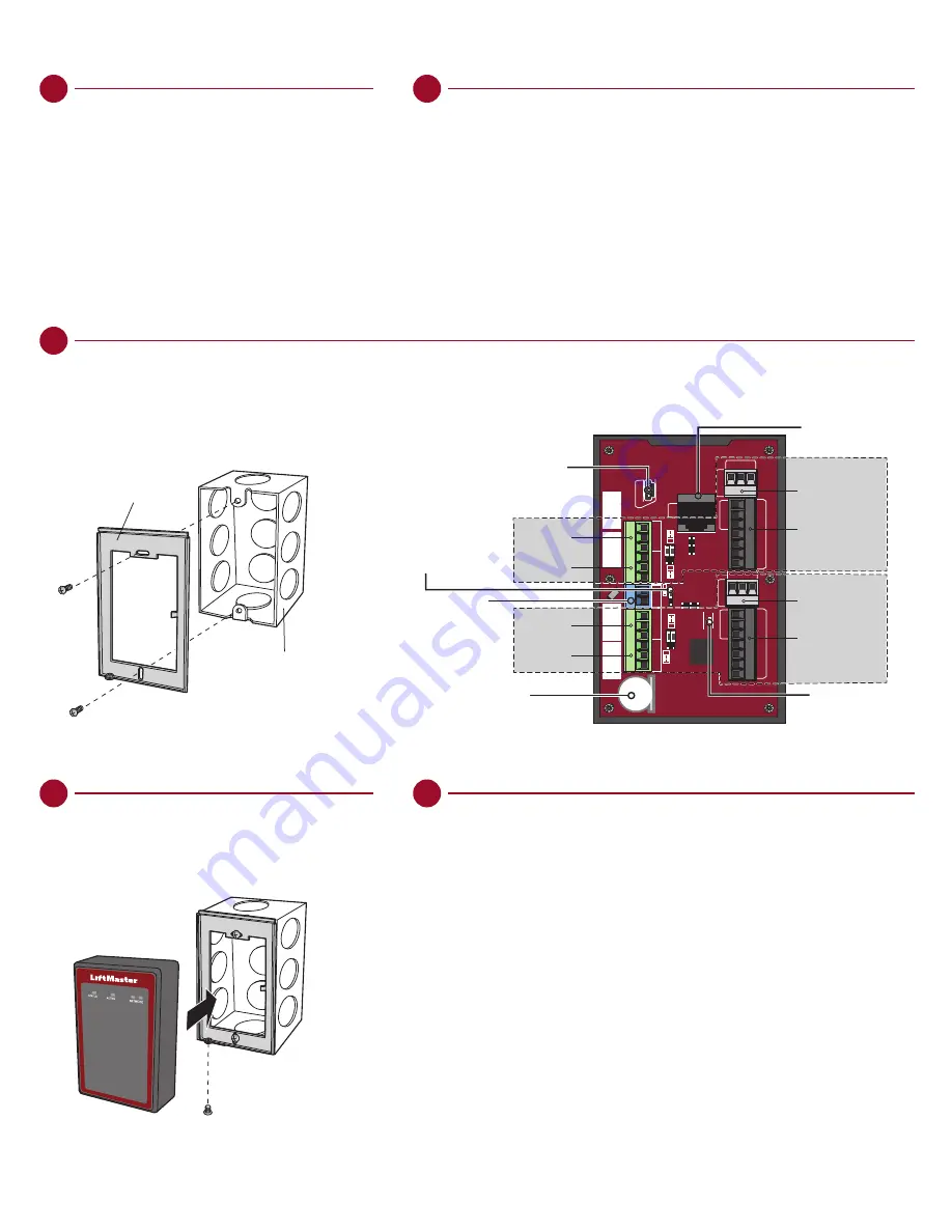
3 . I N S TA L L T H E C A P 2 D
1. Make sure all the wiring is tucked into the electrical box.
2. Slide the CAP2D onto the bracket and secure with the screw
on the bottom of the CAP2D.
4 . VA L I DAT E P R O P E R O P E R AT I O N
Test each credential type and ensure proper behavior of each gate/door connected to CAP2D.
Bracket
Electrical Box
LAN
ADMIN
DR
Y
RL
Y1
WE
T
PSE1
Po
E
DR
Y
WE
T
RL
Y2
HR
TB
T
READER 1
IO 1
REX
CO
M
DOOR
RED GRN 12V BUZ GND D1 D0
IO 2
REX
CO
M
DOOR
READER 2
RED GRN 12V BUZ GND D1 D0
NC
COM
NO
NC
COM
NO
NC
COM
NO
NC
COM
NO
-12IN+
ADMINISTRATIVE USB
DOOR 1
DOOR 2
Auxiliary
Relay 1
REQUEST TO EXIT
STATUS
WIEGAND INPUT
REQUEST TO EXIT
STATUS
WIEGAND INPUT
POWER CONFIG
JUMPER
EXTERNAL
12V POWER
BACKUP LITHIUM
COIN BATTERY (CR1220)
LAN/PoE Connector
LOCAL HEARTBEAT LED
Primary
Relay 1
Auxiliary
Relay 2
Primary
Relay 2
1 . M O U N T T H E B R AC K E T
1. Install an electrical box in the desired mounting location.
2. Remove the bracket from the back of the CAP2D.
3. Mount the bracket to the electrical box.
2 . C O N N E C T AC C E S S C O N T R O L W I R I N G
Route all required wiring into the CAP2D and make necessary connections.
INSTALLATION
SETUP (CONTINUED)
9 . C O N N E C T TO I N T E R N E T
Connect an Ethernet cable to the CAP2D’s LAN port (if using
a PoE port the CAP2D will power up). CAP2D uses DHCP by
default. If a static IP is required, see the full instruction manual.
Power on the CAP2D. The network LED will turn blue when
properly connected to a router or switch.
1 0 . D OW N L OA D DATA B A S E
Confirm setup prior to installation.
Test a valid credential and ensure the relay fires.
Confirm transaction appears in LiftMaster Cloud activity log.
Disconnect power and Internet after settings have been confirmed.


