


6
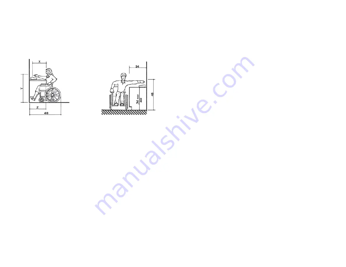
Computer keyboards and other
4.
of
fi
ce equipment should be
placed on desks between 28” – 34” tall with no more than 20
inches in reach depth for obstructed front access or 24 inches in
reach depth for obstructed side reach access. In the
fi
rst
fi
gure
below, if X < 20” then Y = 48”. When X = 20” – 25”, then Y = 44”.
X should always be
≤
25”.
All information contained herein is from the ADA web site and the Department of Justice
Code of Federal Regulations Excerpt CFR Part 36 ADA Standards for Accessible Design
revised July 1, 1994. Chamberlain Access Solutions is not liable for the information contained
in this document and we strongly recommend that installers, owners, and builders work with
quali
fi
ed experts in the local, state, and federal interpretations of ADA and other similar laws.
Refer to the ADA Standards for Accessible Design and Federal regulations for more speci
fi
c
information and requirements.
Figure 5a
Figure 5b
35
TROUBLESHOOTING
For a
New Installation,
the typical problems encountered are related to the
installation or con
fi
guration process. Start at step 1 in the Troubleshooting
Steps section and proceed until the problem is found and resolved.
For an
Existing (previously working) Installation,
the
fi
rst step is to determine
whether anything has been changed at the site. For instance, Has there
been any new construction? This includes any changes to the site,
adding units, recon
fi
guring units, changing or adding video surveillance
components, changing any electrical wiring, roo
fi
ng changes, painting,
etc. Even with a small change, wiring can be disturbed or disconnected or
something new can interfere with equipment operation.
I
•
f there has been new construction, start at step 1 in the
Troubleshooting Steps section and proceed until the problem is
found and resolved.
If the APEX is not working, start at step 1 and proceed until the
•
problem is found and corrected.
If the APEX is receiving power, start at step 4 and proceed until the
•
problem is found and corrected.
Keep thorough notes during troubleshooting to compare against and to
help
fi
nd problems, prevent confusion, and save time if site service by a
technician is required.
Test power and communication
Step 1
Does the APEX Access Device have Power?
Yes – Proceed to step 2
No – Check Power Supply and Wiring and retest or see Multiple
Device Problems
This can be tested quickly by checking the display of the APEX. If the
display is on or if any of the LEDs on the board are on, the board has
power. If there is no indication of power from the display or LEDs, use a
volt meter to check for the presence of voltage on connector P1 pins 1 &
2.
Step 2
Is the voltage at the APEX, connector P1 pins 1 & 2, greater than 10.5
Volts? (Use a volt meter to measure the voltage).
Yes – Proceed to step 3
No – Check Power Supply and Wiring and retest


