background image

27

Care of Your Opener

LIMIT AND FORCE ADJUSTMENTS:

Weather conditions may cause some 
minor changes in door operation 
requiring some readjustments, 
particularly during the fi rst year of 
operation.

Pages 21 and 22 refer to the limit and 
force adjustments. Only a screwdriver 
is required. Follow the instructions carefully.

Repeat the safety reverse test (Adjustment Step 3, 
page 23) after any adjustment of limits or force.

MAINTENANCE SCHEDULE

Every Month

•   Manually operate door. If it is unbalanced or binding, 

call a trained door systems technician.

•   Check to be sure door opens and closes fully. Adjust 

limits and/or force if necessary. (See pages 21 and 22.)

•   Repeat the safety reverse test. Make any necessary 

adjustments. (See Adjustment Step 3.)

Two Times a Year

•   Check chain tension. Disconnect trolley fi rst. Adjust if 

necessary. (See page 7.)

Every Year

•   Oil door rollers, bearings and hinges. The opener does 

not require additional lubrication. Do not grease the 
door tracks.

Every Three to Four Years

•   Use a rag to wipe away the existing grease from the 

garage door opener rail. Reapply a small layer of white 
lithium grease to the rail.

To Open the Door Manually

The door should be fully closed 
if possible. Pull down on the 
emergency release handle and lift 
the door manually. To reconnect 
the door to the opener, press the 
door control push button.

The

 lockout feature

 prevents 

the trolley from reconnecting 
automatically, Pull the emergency 
release handle down and back 
(toward the opener). The door 
can then be raised and lowered 
manually as often as necessary. 
To disengage the lockout feature, 
pull the handle straight down. The 
trolley will reconnect on the next 
UP or DOWN operation.

To prevent possible SERIOUS INJURY or DEATH from 
a falling garage door:
•  If possible, use emergency release handle to 

disengage trolley ONLY when garage door is 
CLOSED. Weak or broken springs or unbalanced 
door could result in an open door falling rapidly and/
or unexpectedly.

•  NEVER use emergency release handle unless garage 

doorway is clear of persons and obstructions.

•  NEVER use handle to pull door open or closed. If 

rope knot becomes untied, you could fall.

LOCKOUT POSITION

Trolley 
Release 
Arm

Emergency 
Release Handle 
(Down and Back)

MANUAL DISCONNECT 

POSITION

Trolley 
Release 
Arm

Emergency 
Release 
Handle 
(Pull Down)

FORCE CONTROLS

LIMIT CONTROLS

Summary of Contents for 3595S 3/4 HP

Page 1: ...operly aligned Periodic checks of the opener are required to ensure safe operation The model number label is located under the light lens on the left side panel of your opener The Chamberlain Group Inc 845 Larch Avenue Elmhurst Illinois 60126 1196 www liftmaster com GARAGE DOOR OPENER Model 3595S 3 4 HP For Residential Use Install on Sectional Doors ONLY THIS OPERATOR IS INTENDED FOR USE ONLY WITH...

Page 2: ...6 To open the door manually 27 Care of your opener 27 Having a problem 28 29 Smart Control Panel messages 30 Programming 31 32 To add or reprogram a hand held remote control 31 To erase all codes 31 3 Button remotes 31 To add reprogram or change a Keyless Entry PIN 32 Repair Parts 33 34 Rail assembly parts 33 Installation parts 33 Motor unit assembly parts 34 Accessories 35 Repair Parts and Servic...

Page 3: ...o garage door and opener ALWAYS disable locks BEFORE installing and operating the opener ONLY operate garage door opener at 120V 60 Hz to avoid malfunction and damage To prevent possible SERIOUS INJURY or DEATH ALWAYS call a trained door systems technician if garage door binds sticks or is out of balance An unbalanced garage door may NOT reverse when required NEVER try to loosen move or adjust gar...

Page 4: ...e bottom of the garage door and the floor MUST NOT exceed 1 4 6 mm Otherwise the safety reversal system may NOT work properly The floor or the garage door MUST be repaired to eliminate the gap Horizontal and vertical reinforcement is needed for lightweight garage doors fiberglass steel aluminum door with glass panels etc See page 19 for details Slack in chain tension is normal when garage door is clo...

Page 5: ...4 14x5 8 2 Washered Bolt 5 16 18x1 2 2 Hex Bolt 1 4 20x5 8 4 Hex Screws 8 32x1 2 Screw 8 32x3 8 Insulated Staples 10 Ring Fastener 3 Drywall Anchors 2 Carriage Bolt 1 4 20x1 2 2 Wing Nut 1 4 20 2 Lock Nut 1 4 20 Lag Screw 1 4 x1 1 2 4 Rope Handle Smart Control Panel 3 Button Remote Control Model 895MAX 1 Remote Control Visor Clip Door Bracket Rail Chain Header Bracket Curved Door Arm Section Strai...

Page 6: ...e bolts fasteners mounted in the top of the opener ASSEMBLY STEP 3 Attach the Chassis Support Bracket Position the rail support bracket on the unit Attach the bracket to the rail with 1 4 20x5 8 hex bolts and lock washers Do not overtighten Attach the bracket to the opener by inserting a 5 16 18x1 2 washered screw through a hole in each side flange and a matching hole in the bracket Complete the co...

Page 7: ...d door may NOT reverse when required and could result in SEVERE INJURY or DEATH 3 ALL repairs to cables spring assemblies and other hardware MUST be made by a trained door systems technician BEFORE installing opener 4 Disable ALL locks and remove ALL ropes connected to garage door BEFORE installing opener to avoid entanglement 5 Install garage door opener 7 feet 2 13 m or more above floor 6 Mount t...

Page 8: ...rsecting horizontal line on the header wall 2 5 cm above the high point This height will provide travel clearance for the top edge of the door To prevent possible SERIOUS INJURY or DEATH Header bracket MUST be RIGIDLY fastened to structural support on header wall or ceiling otherwise garage door might NOT reverse when required DO NOT install header bracket over drywall Concrete anchors MUST be use...

Page 9: ...ADER BRACKET INSTALLATION Extend the vertical centerline onto the ceiling as shown Center the bracket on the vertical mark no more than 6 15 cm from the wall Make sure the arrow is pointing toward the wall The bracket can be mounted flush against the ceiling when clearance is minimal Mark the side holes Drill 3 16 pilot holes and fasten bracket securely to a structural support with the hardware pro...

Page 10: ... onto a stepladder You will need help at this point if the ladder is not tall enough Open the door all the way and place a 2x4 laid flat on the top section beneath the rail If the top section or panel hits the trolley when you raise the door pull down on the trolley release arm to disconnect inner and outer sections Slide the outer trolley toward the motor unit The trolley can remain disconnected u...

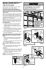
Page 11: ...n line with the header bracket if the bracket is not centered above the door 7 Remove the 2x4 Operate the door manually If the door hits the rail raise the header bracket NOTE DO NOT connect power to opener at this time Figure 1 Figure 2 Figure 3 To avoid possible SERIOUS INJURY from a falling garage door opener fasten it SECURELY to structural supports of the garage Concrete anchors MUST be used ...

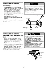
Page 12: ...andard installations ONLY Run bell wire up wall and across ceiling to motor unit Use insulated staples to secure wire in several places DO NOT pierce wire with a staple creating a short or open circuit 4 Strip 7 16 11 mm of insulation from end of bell wire Connect bell wire to the quick connect terminals on the motor unit white to white and white red to red Figure 2 NOTE If you have any trouble wi...

Page 13: ...er end of the rope through the hole in the release arm of the outer trolley Adjust rope length so the handle is 6 feet 1 82 m above the floor Secure with an overhand knot NOTE If it is necessary to cut the rope heat seal the cut end with a match or lighter to prevent unraveling To prevent possible OVERHEATING of the endpanel or light socket DO NOT use short neck or specialty light bulbs DO NOT use ...

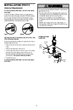
Page 14: ...d Connect the black line wire to the screw on the brass terminal the white neutral wire to the screw on the silver terminal and the ground wire to the green ground screw The opener must be grounded Reinstall the cover To avoid installation difficulties do not run the opener at this time To prevent possible SERIOUS INJURY or DEATH from electrocution or fire Be sure power is NOT connected to the opene...

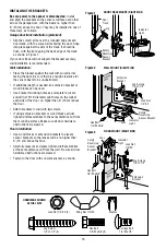
Page 15: ... mounting brackets are designed to clip onto the track of sectional garage doors without additional hardware If it is necessary to mount the units on the wall the brackets must be securely fastened to a solid surface such as the wall framing Extension brackets see accessories are available if needed If installing in masonry construction add a piece of wood at each location to avoid drilling extra ...

Page 16: ...ket mounting holes as a template to locate and drill 2 3 16 diameter pilot holes on the wall at each side of the door no higher than 6 15 cm above the floor Attach brackets to wall with lag screws If using extension brackets or wood blocks adjust right and left assemblies to the same distance out from the mounting surface Make sure all door hardware obstructions are cleared Floor installation Use w...

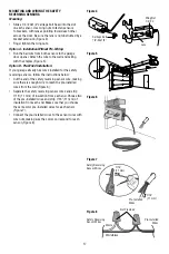
Page 17: ...follow the instructions below Cut the end of the safety reversing sensor wire making sure there is enough wire to reach the pre installed wires from the wall Figure 6 Separate the safety reversing sensor wires and strip 7 16 11 mm of insulation from each end Choose two of the pre installed wires and strip 7 16 11 mm of insulation from each end Make sure that you choose the same color pre installed...

Page 18: ...ensors and opener A broken wire 2 If the sending eye indicator light glows steadily but the receiving eye indicator light doesn t Check alignment Check for an open wire to the receiving eye 3 If the receiving eye indicator light is dim realign either sensor NOTE When the invisible beam path is obstructed or misaligned while the door is closing the door will reverse If the door is already open it w...

Page 19: ...ng holes Secure the door bracket using the two 1 4 14x5 8 self threading screws Figure 2A Alternately use two 5 16 bolts lock washers and nuts not provided Figure 2B Metal insulated or light weight factory reinforced doors Drill 3 16 fastening holes Secure the door bracket using the self threading screws Figure 3 Wood Doors Use top and bottom or side to side door bracket holes Drill 5 16 holes thr...

Page 20: ...e 3 Hole alignment alternative If holes in curved arm are above holes in straight arm disconnect straight arm Cut about 6 15 cm from the solid end Reconnect to trolley with cut end down as shown Bring arm sections together Find two pairs of holes that line up and join with bolts lock washers and nuts Proceed to Adjustment Step 1 page 21 Trolley will re engage automatically when opener is operated ...

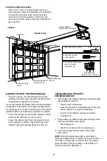
Page 21: ... force as explained in Adjustment Step 2 If the door does not close completely Increase down travel Turn the down limit adjustment screw counterclockwise One turn equals 3 7 5 cm of travel If door still won t close completely and the trolley bumps into the pulley bracket try lengthening the door arm page 20 and decreasing the down limit If the opener reverses in fully closed position Decrease down...

Page 22: ...ce by turning the control clockwise Make small adjustments until the door completes a close cycle After each adjustment run the opener through a complete travel cycle Do not increase the force beyond the minimum amount required to close the door 2 Test the UP open force Grasp the door bottom when the door is about halfway through UP open travel The door should stop If the door is hard to hold or d...

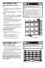
Page 23: ...nt of the opener ADJUSTMENT STEP 4 Test The Protector System Press the remote control push button to open the door Place the opener carton in the path of the door Press the remote control push button to close the door The door will not move more than an inch 2 5 cm and the opener lights will flash The garage door opener will not close from a remote if the indicator light in either sensor is off ale...

Page 24: ...door With a Smart Control Panel this feature may be turned off as follows With the opener lights off press and hold the light button for 10 seconds until the light goes on then off again To restore this feature start with the opener lights on then press and hold the light button for 10 seconds until the light goes off then on again OPERATION IMPORTANT SAFETY INSTRUCTIONS To reduce the risk of SEVE...

Page 25: ...nd that you disable the motion sensor when using the opener lights as working lights Otherwise they will turn off automatically if you are working beyond the sensors range Lock Feature Designed to prevent operation of the door from hand held remote controls However the door will open and close from the Door Control the Outdoor Key Switch and the Keyless Entry Accessories To activate press and hold...

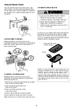
Page 26: ...placing the battery THERE ARE NO OTHER USER SERVICEABLE PARTS Tested to Comply with FCC Standards for Home or office use Operation is subject to the following two conditions 1 this device may not cause harmful interference and 2 this device must accept any interference received including interference that may cause undesired operation The LED s on your remote control will stop flashing when the bat...

Page 27: ...ail Reapply a small layer of white lithium grease to the rail To Open the Door Manually The door should be fully closed if possible Pull down on the emergency release handle and lift the door manually To reconnect the door to the opener press the door control push button The lockout feature prevents the trolley from reconnecting automatically Pull the emergency release handle down and back toward ...

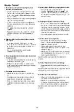
Page 28: ...l garage siding 5 Opener noise is disturbing in living quarters of home If operational noise is a problem because of proximity of the opener to the living quarters the Vibration Isolator Kit 89LM can be installed This kit was designed to minimize vibration to the house and is easy to install 6 The garage door opens and closes by itself Be sure that all remote control push buttons are off Remove th...

Page 29: ...springs may be broken Close the door and use the emergency release handle to disconnect the trolley Open and close the door manually A properly balanced door will stay in any point of travel while being supported entirely by its springs If it does not disconnect the opener and call a trained door systems technician Do not increase the force to operate the opener 15 The opener motor hums briefly the...

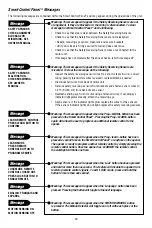
Page 30: ...ach the receiving eye Align sensors if the indicator lights glow replace the wires for the sensors If the sensor indicator lights do not light replace the safety reversing sensors Meaning This message will appear when the Prog LEARN button has been pressed on the Smart Control Panel Pressing the Prog LEARN button again will allow the user to program an additional remote control to the opener Meani...

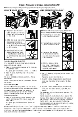
Page 31: ...ght solid then slowly press and release the remote control button again Repeat until the light bulb blinks DO NOT press the button after the light bulb blinks 4 To exit programming mode press any remote control button except the button that was just programmed 2 Press and release the Prog Learn button on the Smart Control Panel twice Within 30 seconds Safety Pin or Paper Clip OR LEDs Learn LED Pro...

Page 32: ...IN then press Enter The door should move To set a temporary PIN You may authorize access by visitors or service people with a temporary 4 digit PIN After a programmed number of hours or number of accesses this temporary PIN expires and will no longer open the door It can be used to close the door even after it has expired To set a temporary PIN 1 Press the four buttons for your personal entry PIN ...

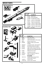
Page 33: ...emote control 3 10A19 3V2016 Lithium battery LED and opener 4 29C151 Remote control visor clip 5 41A2828 Emergency release rope and handle assembly 6 41B4494 1 2 Conductor bell wire white white red 7 41A5047 Door bracket w clevis pin fastener 8 41A4353 Header bracket w clevis pin fastener 9 41A5034 Safety sensor kit receiving and sending eyes with 3 9 m 2 conductor bell wire 10 178B34 Straight doo...

Page 34: ...replacement motor bracket assembly Complete with Motor worm bracket gear case bearing assembly RPM sensor 13 41A5633 13 Cover 14 41A5532 Gear case 15 41A2822 1 Interrupter cup assembly 16 41C4398A RPM sensor assembly 17 41AC075 2S Receiver logic board assembly Complete with Logic board end panel with all labels light socket 18 41C5657 High voltage wire harness 41C6661 Low voltage wire harness 19 4...

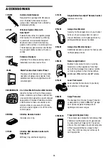
Page 35: ...age door openers against damage from lightning and power surges 902LM 903LM 2 3 Door Multi Function Wall Control Ideal for homes with up to three garage doors Combine up to three controls into one wall control panel for a neat compact appearance Enhanced functions include Lock Feature to lock out outside radio signals while you are away from home and turn opener lights on or off from the control p...

Page 36: ... WARRANTY DOES NOT COVER NON DEFECT DAMAGE DAMAGE CAUSED BY IMPROPER INSTALLATION OPERATION OR CARE INCLUDING BUT NOT LIMITED TO ABUSE MISUSE FAILURE TO PROVIDE REASONABLE AND NECESSARY MAINTENANCE UNAUTHORIZED REPAIRS OR ANY ALTERATIONS TO THIS PRODUCT LABOR CHARGES FOR REINSTALLING A REPAIRED OR REPLACED UNIT REPLACEMENT OF BATTERIES AND LIGHT BULBS OR UNITS INSTALLED FOR NON RESIDENTIAL USE THI...

Reviews: