background image

LIFT-MASTER SERVICE

IS ON CALL

HOW TO ORDER

REPAIR PARTS

OUR LARGE SERVICE Organization

SPANS THE UNITED STATES AND CANADA

Selling prices will be furnished on request or parts will be
shipped at prevailing prices and you will be billed

INSTALLATION AND SERVICE INFORMATION IS AS
NEAR AS YOUR TELEPHONE SIX DAYS A WEEK.
SIMPLY DIAL OUR TOLL FREE NUMBER:

WHEN ORDERING REPAIR PARTS ALWAYS GIVE THE
FOLLOWING INFORMATION:

• PART NUMBER

• PART NAME

• MODEL NUMBER

1-800-654-4736

HOURS: 

7:00 a.m. TO 3:30 p.m.

(Mountain Std. 

Time)

MONDAY through SATURDAY

ADDRESS ORDERS TO:

CHAMBERLAIN MFG.

CANADA INC.

Unit 11 230 Bayview Drive

Barrie Ont. Canada L4N 5E9

For professional installation parts and service contact your
local LIFT-MASTER/CHAMBERLAIN dealer. Look for him in
the Yellow Pages or call our Service number for a list of
dealers in your area.

SERVICE INFORMATION

TOLL FREE NUMBER:

1-800-654-4736

LIFTMASTER GARAGE DOOR OPENER ONE-YEAR LIMITED WARRANTY

The Chamberlain/Lift-Master warrants to the first retail purchaser of this product that it will be free from any defect in materials and/or
workmanship for a period of twelve full months from the date of purchase. The product must be used in complete accordance with Lift-
Master's instructions for installation. or operation and care.

LIMITED WARRANTY ON MOTOR

Model 1160: The motor is warranteed to be free from any defect in materials and/or workmanship for a period of 60 full months (5 years)
from the date of purchase.

Models 1150 and 1145: The motor is warranteed to be free from any defect in materials and/or workmanship for a period of 36 full months
(3 years) from the date of purchase.

This  warranty does not cover non-defect damage caused by unreasonable use (including abuse failure to provide reasonable and
necessary maintenance or any alterations to the product), labor charges for  dismantling or reinstalling of a repaired or replaced unit or
replacement batteries.
If during the warranty period the product appears as though it may be defective CALL OUR TOLL FREE SERVICE NUMBER BEFORE
DISMANTLING IT (1-800-654-4736).
 If the product is then alleged to be defective please send it pre-paid and insured to our Service
Center to obtain warranty repair You will be advised of shipping instructions when you call the number listed above.
Please be sure to include a brief description of the  problem and a dated proof-of-purchase receipt with any product that is returned for
warranty repair.

Product under warranty which upon receipt by Chamberlain/LiftMaster is determined to be defective in materials and/or workmanship will be
repaired or replaced (Chamberlain's option) at no cost to you and returned pre-paid. Defective parts will be repaired or replaced with new or
factory rebuilt parts at Chamberlain's option.
THE DURATION OF IMPLIED WARRANTIES OF MERCHANTABILITY AND FITNESS FOR A PARTICULAR PURPOSE IS 

LIMITED

TO THE DURATION OF THIS WRITTEN WARRANTY. SOME PROVINCES MAY NOT ALLOW LIMITATIONS ON HOW LONG AN
IMPLIED


WARRANTY LASTS SO THE ABOVE LIMITATION MAY NOT APPLY TO YOU.

All claims for consequential or incidental damages for breach of this warranty are excluded and in no event shall manufacturer's liability for
breach of warranty negligence strict liability or breach of contract exceed the cost of the product covered herein but the purchaser is entitled
to the remedies expressly provided in this policy. Some provinces do not allow the exclusion or limitation of incidental or consequential
damages so the above limitation or exclusion may not apply to you.

No representative or person is authorized to assume for us any other liability in connection with the sale of this product. This warranty gives
you specific legal rights and you may also have other rights which may vary from province to province.

1990, Chamberlain Mfg. Canada

Inc. All rights reserved

114A1297

Printed in Mexico

Summary of Contents for 1145-1/3HP

Page 1: ...D TO INSURE SATISFACTORY OPERATION CONTENTS PAGE Safety Rules 2 Carton Inventory 3 Features of Your Opener 3 Specifications 3 Accessories 4 Completed Installation Illustration 5 Installation Informati...

Page 2: ...serious personal injury from entanglement REMOVE ALL THE ROPES CONNECTED TO GARAGE DOOR before installing the garage door opener Install door control button or any additional push buttons IN A LOCATIO...

Page 3: ...ord disconnect permits manual door operation in case of an emergency or power failure 5 Automatic Reconnect Trolley halves reconnect for automatic operation when opener is activated after a manual dis...

Page 4: ...Model 66LM KEYLESS ENTRY SYSTEM Enables homeowner to operate garage door opener from outside by entering code on specially designed keypad THE PROTECTOR SYSTEM Provides auxiliary support to the safety...

Page 5: ...5...

Page 6: ...BROKEN SPRINGS COULD ALLOW AN OPEN DOOR TO FALL RAPIDLY PROPERTY DAMAGE OR SERIOUS PERSONAL INJURY COULD RESULT DO NOT USE THE MANUAL RELEASE HANDLE TO PULL THE DOOR OPEN OR CLOSED HOW THE DOOR MOVES...

Page 7: ...d and properly set when opener is installed Only a screwdriver is required Pages 20 and 21 refer to the limit and force adjustments Follow the instructions carefully REMOTE CONTROL BATTERY The 12 Volt...

Page 8: ...ONLY THESE SCREWS Use of any other screws will cause serious damage to door opener Align T rail and styrofoam over opener sprocket Cut tape from T rail chain and styrofoam REMOVE STYROFOAM Proceed to...

Page 9: ...ten the chain Refer to Page 7 ASSEMBLY OF YOUR GARAGE DOOR OPENER IS NOW COMPLETE BEFORE BEGINNING THE INSTALLATION OF YOUR GARAGE DOOR OPENER BE SURE TO COMPLY WITH ALL THE SAFETY RULES KEEP GARAGE D...

Page 10: ...nside vertical centerline of garage door Extend the line onto header wall above door 2 Open door to highest point of travel as shown Draw an intersecting horizontal line on header wall 2 above high po...

Page 11: ...CLOSED door NOTE If the total number of inches exceeds height available In garage use the maximum height possible On finished ceilings do not position the bracket closer than 1 2 from ceiling POSITIO...

Page 12: ...fficient PROCEDURE Raise the opener onto a stepladder Open garage door Place a 2x4 on the top section of door near centerline as shown Rest T rail on 2x4 as shown INSTALLATION 1 PIECE DOOR WITHOUT TRA...

Page 13: ...f the opener to the structural support Cut both pieces of the hanging bracket to required lengths Flatten one end of each bracket and bend or twist to fit the fastening angles Do not bend at the brack...

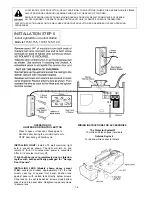
Page 14: ...or close door Press again to REVERSE door during the CLOSING cycle or to STOP door during OPENING cycle To white and black opener terminals Outside Keylock To red and white opener terminals INSTALLIN...

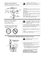
Page 15: ...or will CLOSE if door control button is pressed and held until the door closes fully If button is released before down travel is completed door will reverse TO ACTIVATE Press Lock Switch button Indica...

Page 16: ...AND OPENER MAKE DOOR LOCKS INOPERATIVE BEFORE CONNECTING ELECTRIC POWER USE A WOOD SCREW OR NAIL TO HOLD LOCKS IN OPEN UNLOCKED POSITION THE INSTALLATION THE WIRING MUST BE IN COMPLIANCE WITH LOCAL EL...

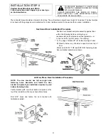
Page 17: ...sition door bracket and plate assembly against door within the following limits according to your requirements and centered on vertical guideline or to one toot left or right of center if necessary A...

Page 18: ...the connection with a ring fastener FIG B Bring arm sections together Find two pairs of holes that line up and join sections Select holes as far apart as possible to increase door arm rigidity Fasten...

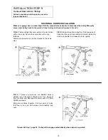
Page 19: ...The arm should touch trolley just in back of door arm connector hole as shown in solid line drawing If arm does not extend far enough adjust limit further One full turn equals 2 of door travel Decreas...

Page 20: ...e 10 Increase DOWN travel Turn down limit adjustment screw counterclockwise One turn equals 2 inches of travel IF OPENER REVERSES IN FULLY CLOSED POSITION Decrease DOWN travel Turn down limit adjustme...

Page 21: ...4 of a complete turn Do not force controls beyond that point Turn force adjustment controls with a screwdriver Adjustment Label FORCE ADJUSTMENT CHART TEST DOWN CLOSE FORCE Grasp the door handle or d...

Page 22: ...When the door reverses on the one inch obstacle remove the obstruction and run the opener through a complete travel cycle Door MUST NOT reverse in closed position Repeat Adjustment Steps 1 2 and 3 if...

Page 23: ...es in your single function remote and any new remote control 2 Place remotes side by side as shown and set switches in ALL remotes to matching positions 0 Use a pen or screwdriver to slide the code sw...

Page 24: ...ures on page 23 ALL remote controls must be set to same code REMOTE CONTROL TRANSMITTER HAS SHORT RANGE 1 Check battery test light If the light is dim change the battery 2 Change the location of the r...

Page 25: ...garage door serviceman to correct the problem OPENER MOTOR HUMS BRIEFLY THEN WON T WORK 1 Garage door springs are broken SEE ABOVE 2 The trolley may be jammed into stop bolts Pull or push on door whil...

Page 26: ...14 2 Strand 4 Strand Bell Wire Bell Wire 217A238 217A241 Multi Function Control Panel 41A3586 Remote Control Transmitter Visor Clip 29C128 Curved Door Arm Section 178B35 Door Bracket Plate 12B380 Door...

Page 27: ...acitor baracket KEY PART NO NO DESCRIPTION 10 41A3150 Terminal block w screws 11 41D3058 Universal replacement motor bracket assy Includes motor worm bracket bearing assy and RPM sensor 12 51R370 Cove...

Page 28: ...for dismantling or reinstalling of a repaired or replaced unit or replacement batteries If during the warranty period the product appears as though it may be defective CALL OUR TOLL FREE SERVICE NUMB...

Reviews: