Quick Start Guide for 3680A/B Cable and Antenna Analyzer
part in Section 3.5 of this Chapter.
8. According to Section 3.1 in this Chapter, calibrate port 1 of Analyzer;
9. Press
【
Freq
】->
[Velo Factor] to set velocity factor of DUT, which is the transmission speed and light
speed of electromagnetic wave in the cable, is between 0~1.
10. Select [Cable Loss] menu, and set cable loss of the measured cable according to the known parameters
of DUT.
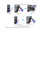
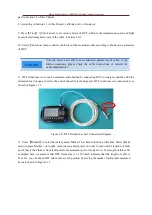
11. DTF return loss curve can be measured and obtained by connecting DUT to Analyzer and then link the
mismatch load or open circuit to the end of the cable (as fault point). DTF return loss test connection is as
shown in Figure 3.11.
Open circuit
Figure 3.11 DTF Return Loss Test Connection Diagram
12. Press
【
Marker
】
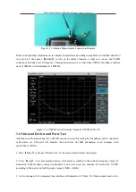
to enter the marker menu, Marker 1 has been turned on at this time. Select [Peak]
menu to place Marker 1 onto peak value (namely fault point), in order to read out the location of fault
point, that is the distance from fault point to measurement port of Analyzer. At 25m length of this cable
exampled here, we measure that DTF return loss is 2.359 which indicates that the length of cable is
25m. Or, you can check DTF return loss at each position by moving the marker. Fault points measured
here are shown in Figure 3.12.
Velocity factor and cable loss are inherent parameters of cable, if any
further questions, please check the cable instructions or consult the
cable manufacturer.
CAUTION


