CEVA Hillcrest Labs FSP200 Quick Start Manual Download Page 6

December 2018 

1000-4298 Revision 1.0 


www.ceva-dsp.com 

© 2019 CEVA, Inc.  All rights reserved


6 / 11


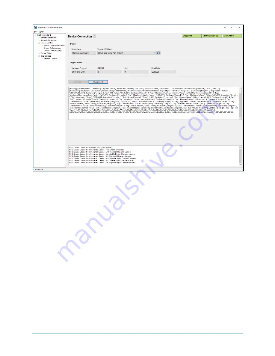
Figure 7: Device Connection Window after Successful Communication in Freespace™ MotionStudio 2 

When connection process is completed, the three status indicator text boxes on the upper right corner 
of the panel and the console window on the bottom provide the result of connection process. The three 
status indicators show the status of the connected system and the status of the associated panel. If the 
specific panel supports the protocol used by the connected device, the panel becomes active and shows 
in green color. 

Sensor Control 

The Sensor Control panel allows the user to enable and disable the various sensors individually. There 
are two ways to control sensors: 


To enable an individual sensor at a default operation rate, use the check box on the right end of 
the row for each sensor.  


To enable sensors at specific rates, input the requested operating period, in microseconds, in 
the 'Requested Period (us)" fields. Then click the "Set Sensor Periods" button on the top of the 
panel. All sensors will be updated with the specified operating period. The "Requested Period 
(us)" fields which are left blank or have invalid values are assumed to be "zero". 

In many cases, the sensors do not operate at the exact rate as requested. The actual operating period is 
shown in the "Reported Period (us)" field. Users can also use the "Get Sensor Periods" button on top of 
the panel to refresh the actual operating period for all sensors. 


Summary of Contents for Hillcrest Labs FSP200

Page 1: ...th software provided by Hillcrest to facilitate customer evaluation 1 Hardware 1 1 Introduction The FSP200 Serial USB Adapter board includes the FSP200 reference module with Bosch BMI055 6 axis sensor that is designed for quick and easy evaluation and prototyping Figure 1 FSP200 USB Serial adapter board 1 2 Connections The FSP200 communicates with the host system over a UART interface either in UA...

Page 2: ... USB Type A to Micro B cable Freespace MotionStudio 2 application available in https www hillcrestlabs com downloads freespace motionstudio 2 Connect USB Type A to Micro B cable to FSP200 Serial USB Adapter board and your PC The USB Serial COM port should appear in your Device Manager after the driver is installed properly Figure 2 Device Manager for USB Serial Port Please note the configurations ...

Page 3: ...on to bring up the Advanced Settings window In the Advanced Settings window change the default the Latency Timer from 16 msec to 1 msec Figure 4 Advanced Setting for COM Port 2 1 2 Running FreespaceÔ MotionStudio 2 Start Freespace MotionStudio 2 After you unzip the PC Application package launch MotionStudio2 exe under MotionStudio2 folder This will open MotionStudio2 window ...

Page 4: ...FSP200 Serial USB Adapter Board From the menu panel on the left select Device Connection This panel allows users to select device type transport protocol and more Device Type of the bridge is set to FTDI Adapter Board Virtual COM Port available in your PC appears in COM9 USB Serial Port box Target Device set to SHTP over UART default S1 setting Use Connect button to start ...

Page 5: ...December 2018 1000 4298 Revision 1 0 www ceva dsp com 2019 CEVA Inc All rights reserved 5 11 Figure 6 Device Connection Panel in Freespace MotionStudio 2 ...

Page 6: ...el allows the user to enable and disable the various sensors individually There are two ways to control sensors To enable an individual sensor at a default operation rate use the check box on the right end of the row for each sensor To enable sensors at specific rates input the requested operating period in microseconds in the Requested Period us fields Then click the Set Sensor Periods button on ...

Page 7: ...l move according to the device orientation To adjust the camera position move the cursor to the Virtual Object Panel then press the LEFT mouse button Hold the button down and move the mouse to change the view position To reset the camera position use the Reset Camera Position button To display the Game Rotation Vectors select the GameRotationVector from the drop down menu the data fields should st...

Page 8: ...SB Adapter Board Orientation Please follow the instructions below to align your device Enable Game Rotation Vector in Sensor Control panel Switch to Virtual Object panel and move the background so the black corner of the Hillcrest logo on the ground plane points to your forward direction heading Hold the FSP200 Serial USB Adapter board Y axis points to your forward direction ...

Page 9: ... Inc All rights reserved 9 11 Select GameRotationVector in drop down menu and click Tare Z Now the sword will point to the edge of the Hillcrest logo and is aligned with your device Y Figure 11 Sensor Orientation in Virtual Object Panel in Freespace MotionStudio 2 ...

Page 10: ...vision 1 0 www ceva dsp com 2019 CEVA Inc All rights reserved 10 11 References 1 1000 4121 FSP200 Datasheet Hillcrest Labs 2 1000 3625 SH 2 Reference Manual Hillcrest Labs 3 1000 3535 Sensor Hub Transport Protocol Hillcrest Labs ...

Page 11: ...d to be accurate and reliable However the information is provided AS IS without any express or implied warranty of any kind including warranties of merchantability non infringement of intellectual property or fitness for any particular purpose In no event shall CEVA or its suppliers be liable for any claims and or damages whatsoever arising out of the use of or inability to use the materials CEVA ...

Reviews: