background image

Contents 


OMEGA Mifare wall terminals 


Contents 

Preface .......................................................................... 2


Notes on the layout ....................................................... 2


For your safety .............................................................. 5


 Basic safety instructions .......................................... 5


Explanation of the safety notes ....................................... 8


Intended use ................................................................ 9


Remarks ...................................................................... 9


Manufacturer ................................................................ 9


Service ........................................................................ 9


Introduction ................................................................ 10


Description .................................................................. 10


Optional Master media .................................................. 14


Programming with OMEGA software ................................ 16


System components ..................................................... 18


Versions and their functions........................................... 19


Scope of delivery .......................................................... 20


Unpacking the wall terminals ......................................... 20


Connections ................................................................. 23


Fitting the wall terminals ............................................ 31


Disassembly of the wall terminals ................................... 33


Fastening the fitting frame of the wall terminals ............... 35


Fitting the WT-M-I wall terminal ..................................... 37


Fitting the WT-M-II wall terminal .................................... 40


Summary of Contents for WT-M-I

Page 1: ...OMEGA Mifare wall terminals WT M I WT M II Fitting and Operating Instructions Translated fitting and operating instructions version 1 42 09 2012...

Page 2: ...ll terminals must have read and understood the entire contents of these Fitting and Operating Instructions These Fitting and Operating Instructions should be kept near the wall terminals at all times...

Page 3: ...9 Introduction 10 Description 10 Optional Master media 14 Programming with OMEGA software 16 System components 18 Versions and their functions 19 Scope of delivery 20 Unpacking the wall terminals 20...

Page 4: ...cking medium 51 Maintenance 52 Spare Parts 52 Trouble shooting 53 Disposal 54 Technical data 55 WT M I WT M II CES standard 55 WT M I WT M II Flush installation 56 Appropriate power supply 58 WT M I W...

Page 5: ...he wall terminals that both the wall terminals and all other system components are in perfect working order Malfunctions of the wall terminals and other system components may compromise the functionin...

Page 6: ...bserved Always have repairs performed by properly qualified personnel Only use accessories and spare parts recommended by CEStronics Do not use any drilling machines or cordless screwdrivers when fast...

Page 7: ...the wall terminals in rooms with a high level of dust formation Do not use the wall terminals near sources of heat Do not expose the wall terminals to temperatures below 25 C or above 70 C Danger of m...

Page 8: ...tructions include safety notes of the following types DANGER DANGER notes warn against hazards that may directly result in severe or fatal injuries CAUTION CAUTION notes warn against hazards that may...

Page 9: ...y damage or even personal injury CEStronics GmbH does not accept any liability for any damage resulting from improper use Remarks These mounting and fitting instructions are only valid for CEStronics...

Page 10: ...g medium within a range of up to 50 mm If an authorized locking medium is found the wall terminal opens within 300 ms All Mifare transponder media and media according to ISO 14443A and DESFire EV 1 ca...

Page 11: ...perations back to the server Thanks to its structure a wireless system combines a high level of operating convenience with low administrative expense It also reduces personnel expenses since virtually...

Page 12: ...cause the sending and receiving frequencies of the reader will be detuned by the magnetic properties of the metals Depending on the metal material the reading range of the wall terminal may be reduced...

Page 13: ...ing range up to 50 mm Programming with optional Master media Different optional Master media available to increase the functionality of the wall terminal see page 13 ff Online programming via 868 MHz...

Page 14: ...ach locking system there is one and only one valid SYSTEM MASTER With the SYSTEM MASTER you can authorize up to ten PROGRAM MASTERS In its basic version a locking system requires one SYSTEM MASTER and...

Page 15: ...g time of your wall terminals During the opening time the wall terminals allow free access The opening time is the period during which the relay is pulled up When the access terminal detects a TIME MA...

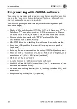
Page 16: ...t 1 GB of free hard disk space Network interface card with TCP IP protocol for the installation with Access Points CD ROM drive for installing the software from data media One free USB port for the us...

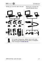
Page 17: ...e wall terminals 17 Setting up a online radio network Setting up a system for manual programming For further information please refer to the User Manual of the CEStronics Suite which is available free...

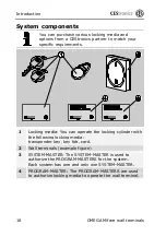
Page 18: ...king media You can operate the locking cylinder with the following locking media transponder key key fob card 2 Wall terminals example figure 3 SYSTEM MASTER The SYSTEM MASTER is used to authorize the...

Page 19: ...mming with programmer programming without time zones and events T Time programming with programmer programming with time zones and events NET With RF modul for use within CEStronics RF networks In pre...

Page 20: ...mptly if any damage is found Satisfy yourself that you have received the version you ordered Also check that the delivered housing version is correct and undamaged Unpacking the wall terminals Take th...

Page 21: ...Introduction OMEGA Mifare wall terminals 21 WT M I 1 Wall terminal type WT M I housing CES Standard 2 Fitting frame 3 2 universal screws 2 5 20 mm 4 2 fastening screws 3 30 mm with 2 plugs...

Page 22: ...be established see page 26 ff 1 Reader terminal outside terminal for wall terminal type WT M II housing CES Standard 2 Fitting frame 3 Controller terminal type WT M II inside terminal with cable for...

Page 23: ...of injury by improper mounting work Ensure that the wall terminals are only wired by skilled electricians or CEStronics partners trained on the product WT M I 1 Screw terminal for relay 2 2 Screw term...

Page 24: ...ay 2 relay contact C 6 Screw terminal for relay 2 relay contact NO 7 Screw terminal for relay 1 relay contact C 8 Screw terminal for relay 1 NO contact 9 Screw terminal for relay 1 NC contact 10 Screw...

Page 25: ...Introduction OMEGA Mifare wall terminals 25 Ensure that the permissible RF ranges are observed As soon as an authorized locking medium grants access the relays are switched...

Page 26: ...Introduction 26 OMEGA Mifare wall terminals WT M II...

Page 27: ...nal RxD TxD Reader terminal Controller terminal TxD RxD Reader terminal NOTICE The wall terminal may be damaged by incorrect power supply Do not connect the reader terminal with any power supply other...

Page 28: ...al for relay 2 relay contact C 6 Screw terminal for relay 2 relay contact NO 7 Screw terminal for relay 1 relay contact C 8 Screw terminal for relay 1 NO contact 9 Screw terminal for relay 1 NC contac...

Page 29: ...tions WT M II Reader terminal 1 Screw terminal GnD to control unit terminal 1 2 Screw terminal RxD to control unit terminal 3 3 Screw terminal TxD to control unit terminal 2 4 Screw terminal VCC to co...

Page 30: ...hat the permitted RF ranges and cable lengths are not exceeded As soon as an authorized locking medium grants access the relays are switched GnD Ground terminal TxD Transmit Data terminal RxD Receive...

Page 31: ...static charges Do not fit the wall terminals in rooms with built up static charge Ensure potential equalization when working on the wall terminal to remove any static charge The wall terminals may on...

Page 32: ...tisfy yourself that the selected wall terminal is suitable for your door system Contact the manufacturer of the door system in case of doubt Ensure that the distance between any two readers is at leas...

Page 33: ...sing For the WT M II wall terminal you must perform the following steps also for the reader module Disassembly may vary depending on the ordered housing version The following tool is required Screwdri...

Page 34: ...s 34 OMEGA Mifare wall terminals To do so insert the slotted head screwdriver into the recess as shown below Lift off the cover You can now fit the control module through the two oblong holes This com...

Page 35: ...for the wall terminal in the CES standard housing Follow the steps for disassembling the wall terminal on pages 33 The selection of the fasteners depends on the material of the wall or ceiling etc on...

Page 36: ...on in wall switch boxes Only use the oblong mounting holes for fastening the fitting frame Ensure that all cables required for the connection are guided through the fitting frame without being damage...

Page 37: ...onnections must already be available in the switch box The supplied fitting frame is not required in this case If you are using fitting frames please follow the fastening instructions on page 35 ff En...

Page 38: ...rminal with two 2 5 20 mm universal screws on the in wall switch box Ensure that the two LEDs 1 of the wall terminal are at the top when the wall terminal is fastened Push the cover on to the control...

Page 39: ...Fitting the wall terminals OMEGA Mifare wall terminals 39 Push the cover onto the control module exerting only a slight pressure This completes the fitting of the WT M I wall terminal...

Page 40: ...tch boxes All required cable connections must already be available in the switch boxes The supplied fitting frame is not required in this case If you are using fitting frames please follow the fasteni...

Page 41: ...St Y 2 2 0 6 mm cables for the connection between the control unit and the reader module The mounting holes of the wall terminal must always be aligned horizontally also when the wall terminal is inst...

Page 42: ...ol module and the reader module as shown in the following figures Insert the cover into the respective recesses Push the covers onto the control module and the reader module exerting only a slight pre...

Page 43: ...eader The maximum distance is 50 mm The green LED in the wall terminal goes on to signal enable status and the connected door system opens During the set opening time you can pass through the door Dur...

Page 44: ...n between the locking device and the locking medium is encrypted Only locking media that are authenticated by the device are authorized to lock or unlock This ensures a very high protection against ma...

Page 45: ...of the wall terminal This distance is about 50 mm The reader module 2 identifies the locking medium The wall terminal sends a short signal to signal the enable status During the opening time you can...

Page 46: ...the software from data media One free USB port for the use of the programming cable optional Monitor with a resolution of 1 024 768 pixel or higher or a resolution of 1 024 600 pixel netbook CEStroni...

Page 47: ...A Mifare wall terminals 47 Further information on the installation and use of the Mifare software can be found in the OMEGA Software Operating Instructions which are available free of charge at www ce...

Page 48: ...mple shows the procedure for the CES standard housing Proceed accordingly for the other housing series to gain access to the interface for the programming cable Proceed as follows Release the cover ca...

Page 49: ...ramming cable 1 into the interface 2 on the board of the wall terminal Start OMEGA Mifare Client and log in Perform the desired operation create locking plan manage devices and media etc Connect the U...

Page 50: ...s which are available free of charge at www ces eu The programming of your wall terminal starts automatically One after the other the following messages appear A locking device wall terminal has been...

Page 51: ...medium has been lost have the wall terminal initialized only by persons trained on the product by CEStronics or a CEStronics partner Always keep all Master media at a safe place Make sure that these...

Page 52: ...terminals serviced and their perfect functioning verified every six months by CEStronics or by a CEStronics partner only Spare Parts The wall terminals does not require any spare parts for you to cha...

Page 53: ...ng medium Use an authorized locking medium The power supply is interrupted Re establish the power supply Verify the perfect functioning of the power circuit of your connected door system The locking m...

Page 54: ...t recycling and or the proper disposal of the device in line with environmental regulations Our packaging is made of environmentally friendly reusable materials These are external packaging and insert...

Page 55: ...55 Technical data WT M I WT M II CES standard Dimensions for CES standard housing Dimensions WT M I u WT M II Fitting frame Length approx 84 mm Width approx 84 mm Height approx 19 mm Length approx 84...

Page 56: ...rox 66 mm Width approx 66 mm Height approx 18 mm Power supply 8 28 V AC DC 150 mA Suitable transponder media Mifare Classic Standard 1k 4k all media according to ISO 14443 DESFire EV 1 Connections scr...

Page 57: ...0 C Controller terminal WT M I WT M II 25 C to 70 C Humidity Max 95 not condensed Environmental conditions Not suitable for use in corrosive atmospheres chlorine ammonia lime water Communication frequ...

Page 58: ...als Appropriate power supply The following power packs are recommended as power supplies for the WT M I and WT M II wall terminals Part number 247723 12 V DC 1 A Part number 247724 12 V DC 800 mA WT M...

Page 59: ...Technical data OMEGA Mifare wall terminals 59 WT M I WT M II IP 55 surface installation optional WT M I WT M II IP 55 Flush installation optional Alle Ma e in mm...

Page 60: ...status Rx Tx Gnd Connections for linking the wall terminal with the long range reader Rx Receive Data Receive signal Tx Transmit Data Transmit signal Gnd Ground VCC Common Connector Voltage terminal...

Page 61: ...Signal Start of programming Beeper LED green 1 short On as long as medium is within range End of programming Beeper LED green 1 long On as long as medium is within range Acknowledgement of programming...

Page 62: ...rk Meaning Signal type Signal Enabling RF mode Beeper LED green 1 short after leaving reading range On as long as medium is within range Disabling RF mode Beeper LED green 1 long after leaving reading...

Page 63: ...m is within range Disabling learning mode Beeper LED green 1 long after laving reading range On as long as medium is within range Learning mode enabled LED green 1 short Acknowledgement of learning mo...

Page 64: ...amage caused by faulty backups damage as a consequence of external events or influence damage as a consequence of improper operation damage as a consequence of excess voltage damage as a consequence o...

Page 65: ...1 204 229 info ces locks de CESitalia srl V d vecchie Fondamenta 4 Stra e d A Gr ndungen 4 I 39044 Egna Neumarkt BZ 39 0471 812 294 39 0471 812 294 info it ces eu www ces eu it CESrom srl Str Metalurg...

Reviews: