Cerwin-Vega CVXL-112 Instruction Manual Download Page 8

CERWIN-VEGA PROFESSIONAL 


8


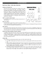
Rear Panel - Mixer - CVXL-112, CVXL-115, CVXL-215 


INPUT 1, INPUT 2, INPUT 3 GAIN KNOBS 

Each knob adjusts the gain level on the respective input signal.  The 
full  clock-wise  position  (MAX)  sets  the  gain  level  to  maximum 
whereas a full counter-clockwise (MIN) position sets the gain level 
to the minimum ‘MUTE’ level.  It is recommended to set each level 
knob to the middle position and the Main Level knob to the MIN or 
fully counter-clockwise position when first connecting the system.   

INPUT 1, INPUT 2 MIC/LINE SWITCH ES 

Set each switch according to the equipment connected to INPUT 1 
and INPUT 2.  For example, if a microphone is connected to INPUT 
1, set the switch to ‘MIC’.  If a mixing console or acoustic-electric 
guitar is connected then set the switch to ‘LINE’. 


NOTE: The input switch must be properly set to the device that is connected to the input.  Any 
mistake may result in unexpected sound level. 

SIGNAL/CLIP INDICATORS 

Each of the three inputs is monitored by an indicator that provides status on the incoming audio signal.  The SIGNAL 
indicator is illuminated when there is an audio signal present with a level greater than -30dBu.  The CLIP indicator is 
illuminated when the audio signal is clipping and adjustments must be made to avoid amplifier shutdown and poor 
sound quality.  Adjustments to prevent clipping are made by reducing the input signal gain/level on the appropriate 
channel or reducing the volume level on your audio source, if possible. 

INPUT 1 & INPUT 2 INPUT JACKS  

A combination input on each channel allows for either XLR or ¼” TRS cable types.  

 
INPUT 3 INPUT JACKS 

A pair of ¼” TS unbalanced input jacks is provided on this channel for stereo connections such as a keyboard or 
media device.  Devices with RCA outputs can use these inputs with the appropriate cable or plug adapter.  Both 
input jacks on this channel are summed into one mono signal. 

 
THRU 1 & THRU 2 

The balanced XLR outputs THRU 1 & THRU 2 are parallel connections to the respective INPUT 1 and INPUT 2.  The level 
controls for INPUT 1 & INPUT 2 will not affect the signal on the direct output connection.  

MIX OUTPUT 

This is a balanced XLR output that is a sum of all three input channels.  This output is not affected by changes to the 
Main Level knob or the custom features but is affected by the levels set on each channel gain knob.  This connection 
is designed to provide an output which combines all three input channels together for connecting to another CVXL 
powered speaker or a recording device.   


Summary of Contents for CVXL-112

Page 1: ...CVXL SERIES MANUAL Instruction Manual English CVXL 112 CVXL 115 CVXL 215 CVXL 118s and CVXL 218s Powered Loudspeakers...

Page 2: ...Using the CVXL 112 as a floor stage monitor 13 Using the pole mount CVXL 112 CVXL 115 only 14 Using suspension points CVXL 112 CVXL 115 CVXL 215 only 15 Application 1 Single CVXL 112 CVXL 115 or CVXL...

Page 3: ...should be installed so that its location or position does not interfere with its proper ventilation For example it should not be situated on a bed sofa rug or similar surface that may block the venti...

Page 4: ...lified service personnel when any of the following happens The power cord or the plug has been damaged Objects have fallen onto or liquid has been spilled into the unit The unit has been exposed to ra...

Page 5: ...hese limits are designed to provide reasonable protection against harmful interference in a residential installation This equipment generates uses radiates radio frequency energy and if not installed...

Page 6: ...the speaker cone or surround Cerwin Vega does not support suspension of the subwoofer models covered in this manual Cerwin Vega speakers can generate considerable vibrational energy When placed on a s...

Page 7: ...using the loudspeaker set the POWER switch to the OFF position BEFORE removing any cables or turning off the source audio equipment Loudspeaker Placement Never point a microphone directly at the louds...

Page 8: ...0dBu The CLIP indicator is illuminated when the audio signal is clipping and adjustments must be made to avoid amplifier shutdown and poor sound quality Adjustments to prevent clipping are made by red...

Page 9: ...itch adjusts the contour of the overall frequency response optimizing the speaker for use as either a stage monitor CVXL 112 for vocal reinforcement CVXL 115 CVXL 215 or a main sound system CVXL 112 C...

Page 10: ...connecting to an additional powered speaker MAIN LEVEL KNOB REMOTE VOLUME CONTROL It is highly recommended to have the volume set to the minimal MIN level upon initial system start up and it can be ad...

Page 11: ...rd to face the stage and switched to CARDIOID MODE This will reduce the volume of the subwoofers for the performers on stage while still projecting good low frequency coverage toward the audience This...

Page 12: ...mage to the fuse and or loudspeaker AC POWER INLET FUSE The power inlet is an IEC receptacle type and should only be used with the provided or equivalent rated power cord Below the power inlet is the...

Page 13: ...gle toward the performers It is recommended to use MONITOR mode for this application as it reduces the volume of frequencies that are prone to feedback Be sure that the loudspeaker and cables are not...

Page 14: ...he speakers when moved or pulled Before loudspeaker pole mounting be sure to inspect all critical points for cracks deformations corrosion and or missing parts that may affect the strength and safety...

Page 15: ...point can also be used for speaker pullback To suspend a loudspeaker remove the M10 countersunk fly bracket screws in the fly points where you want to install M10 eye bolts Screw in the M10 eye bolts...

Page 16: ...es qualified persons who are familiar with rigging standards and practices Any unsafe mounting of any heavy load can result in serious injury and equipment damage Consult a licensed professional engin...

Page 17: ...r are used together Each individual channel volume can be adjusted to create the right balance while the main volume knob controls the overall audience volume Connection Equipment Cable Type Input 1 o...

Page 18: ...an appropriate setting on the first speaker Be aware that the main volume on the first speaker will not change the volume on the second speaker so make sure to set the input and main volume knobs to s...

Page 19: ...nd then the signal is linked to the CVXL 112 CVXL 115 or CVXL 215 speakers by using the CVXL 118s CVXL 218s THRU 1 and THRU 2 outputs For the best sound make sure to set the filter switches on each sp...

Page 20: ...the signal is linked to the CVXL 112 CVXL 115 or CVXL 215 speakers by using the CVXL 118s CVXL 218s THRU 1 outputs For the best sound make sure to set the filter switches on each speaker as indicated...

Page 21: ...ng good audience coverage The diagram and tables below show how to connect two CVXL 118s CVXL 218s subwoofers using cardioid mode Subwoofer Connection Equipment Cable Type Audience Input 1 and or 2 Fr...

Page 22: ...nd tables below show how to connect three CVXL 118s CVXL 218s subwoofers using cardioid mode Subwoofer Connection Equipment Cable Type Audience 1 Input 1 and or 2 From Audio Source Line Level XLR TRS...

Page 23: ...o the next CVXL 112 CVXL 115 or CVXL 215 Any additional speakers should connect Input 1 to Mix Out of the previous speaker Connection Equipment Cable Type Input 1 or 2 Microphone Set switch to MIC XLR...

Page 24: ...to the preferred presentation for the audience The performer s monitor can be mixed to the performer s specific requirements without affecting what the audience hears NOTE Careful positioning of the m...

Page 25: ...se engineer has control of the entire sound reinforcement system using the console mixer The diagram below shows how a console mixer interfaces with the performers on stage audio equipment with severa...

Page 26: ...cured tightly to prevent rattling during general use Remote Main Volume The 3 pin terminal connector plug allows any CVXL loudspeaker main volume level to be controlled from a remote location through...

Page 27: ...oudspeaker input is correct Verify that the MUTE switch on the audio mixer is disengaged Verify that an external power source is used with microphones that require phantom power No Power No connection...

Page 28: ...that the connectors are clean and free of any residue buildup Verify that the insulation jackets on all cables have not been torn or crushed Rattling Sounds Be sure that the rattling sounds do not com...

Page 29: ...er can be maintained cosmetically by using a dry cloth Avoid using cleaning chemicals as they may harm the finish of the loudspeaker A direct burst of air should be avoided since it could harm the dri...

Page 30: ...CERWIN VEGA PROFESSIONAL 30...

Page 31: ...Audio or one of Gibson Pro Audio s Authorized Service Centers in the US will repair the defect s or replace the merchandise as it deems appropriate at its sole discretion Warranty Period from date of...

Page 32: ...orized dealer or upon which unauthorized repair or service has been performed GIBSON MAKES NO OTHER EXPRESS WARRANTY OF ANY KIND WHATSOEVER ALL IMPLIED WARRANTIES INCLUDING WARRANTIES OF MERCHANTABILI...

Page 33: ...ms liability for defects or damage caused by services performed by unauthorized persons or non warranty service not performed by Gibson or an Authorized Gibson Pro Audio Service Center When contacting...

Reviews: