Cerwin-Vega CVXL-112 Instruction Manual Download Page 28

CERWIN-VEGA PROFESSIONAL 


28


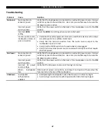
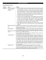
Troubleshooting (continued) 

Problem 

Cause  

Solution 

Bad Sound 

Incorrect equipment 
settings, causing 
distortion 


Check the meters on the external mixing console to ensure that the signal is 
not  being  clipped  by  the mixer.   If  the  levels  from the  mixer  are  too  high, 
correct the gain structure of the console, first by lowering the pre-amplifier 
trim (input sensitivity).  If this does not lower the signal level sufficiently, then 
lower the channel faders.  If the level is still too high, then lower the master 
bus; however, a clipped input is most likely the source of the distortion.  It is 
important to check every active input channel on the console to ensure that 
each input trim is set correctly for each source. 


If the signal sources are plugged directly into the speaker, make sure that the 
input levels are not turned up too high.  If the signal indicator LED is turning 
red on any channel, this indicates that the input on that channel is clipping 
and  that  the  input  level  needs  to  be  lowered.    It  is  also  possible  that  the 
source level needs to be lowered.  If distortion is still audible after lowering 
the source level and input level, then lower the master volume.  


Check  that  the  audio  source  and/or  mixer  do  not  have  excessive  bass  or 
treble  added  to  the  mix,  as  overdriven  EQs  can  clip,  causing  audible 
distortion. 


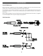
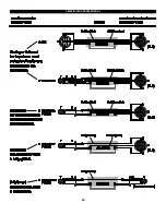
Cable connections  are 
bad. 

Verify that all connections are good.  Verify that the connectors are clean and 
free of any residue buildup.  Verify that the insulation jackets on all cables have 
not been torn or crushed. 


Rattling Sounds 

Be sure that the rattling sounds do not come from the caster wheels (subwoofer 
only), loudspeaker stands, or any furniture or fixtures located near the system. 


Bad  AC  mains  cable 
location 

Avoid using an AC power source that is connected to a light dimmer.  Use an AC 
filter box, or use a different AC circuit.  
Avoid routing the audio signal cables along other power cables, transformers, 
or signal cables to prevent interference. 


Ground loop hum 

Turn all volume and input levels to their minimum settings to verify there is no 
hum coming from the connected audio equipment.  If the hum is still present, 
then remove all audio cable connections; if the hum disappears, then there is a 
potential ground loop problem.  Ground lifting the signal cable (with a direct box 
or  coupling  transformer)  is  the  safest  way  to  eliminate  ground  loops  within 
sound setups.  Plug all audio equipment AC power connections into the same 
outlet, which shares a common ground (make sure that the outlet is capable of 
supporting the power draw of the equipment to avoid overloading the circuit). 
Verify that the distance between AC power source and common ground is as 
short as possible. 


Equipment hiss 

Use a balanced connection to take advantage of the best noise rejection. 
Plug  all  audio  equipment  AC  power  connections  into  the  same  outlet  which 
shares a common ground (make sure that the outlet is capable of supporting the 
power draw of the equipment to avoid overloading the circuit). 


Summary of Contents for CVXL-112

Page 1: ...CVXL SERIES MANUAL Instruction Manual English CVXL 112 CVXL 115 CVXL 215 CVXL 118s and CVXL 218s Powered Loudspeakers...

Page 2: ...Using the CVXL 112 as a floor stage monitor 13 Using the pole mount CVXL 112 CVXL 115 only 14 Using suspension points CVXL 112 CVXL 115 CVXL 215 only 15 Application 1 Single CVXL 112 CVXL 115 or CVXL...

Page 3: ...should be installed so that its location or position does not interfere with its proper ventilation For example it should not be situated on a bed sofa rug or similar surface that may block the venti...

Page 4: ...lified service personnel when any of the following happens The power cord or the plug has been damaged Objects have fallen onto or liquid has been spilled into the unit The unit has been exposed to ra...

Page 5: ...hese limits are designed to provide reasonable protection against harmful interference in a residential installation This equipment generates uses radiates radio frequency energy and if not installed...

Page 6: ...the speaker cone or surround Cerwin Vega does not support suspension of the subwoofer models covered in this manual Cerwin Vega speakers can generate considerable vibrational energy When placed on a s...

Page 7: ...using the loudspeaker set the POWER switch to the OFF position BEFORE removing any cables or turning off the source audio equipment Loudspeaker Placement Never point a microphone directly at the louds...

Page 8: ...0dBu The CLIP indicator is illuminated when the audio signal is clipping and adjustments must be made to avoid amplifier shutdown and poor sound quality Adjustments to prevent clipping are made by red...

Page 9: ...itch adjusts the contour of the overall frequency response optimizing the speaker for use as either a stage monitor CVXL 112 for vocal reinforcement CVXL 115 CVXL 215 or a main sound system CVXL 112 C...

Page 10: ...connecting to an additional powered speaker MAIN LEVEL KNOB REMOTE VOLUME CONTROL It is highly recommended to have the volume set to the minimal MIN level upon initial system start up and it can be ad...

Page 11: ...rd to face the stage and switched to CARDIOID MODE This will reduce the volume of the subwoofers for the performers on stage while still projecting good low frequency coverage toward the audience This...

Page 12: ...mage to the fuse and or loudspeaker AC POWER INLET FUSE The power inlet is an IEC receptacle type and should only be used with the provided or equivalent rated power cord Below the power inlet is the...

Page 13: ...gle toward the performers It is recommended to use MONITOR mode for this application as it reduces the volume of frequencies that are prone to feedback Be sure that the loudspeaker and cables are not...

Page 14: ...he speakers when moved or pulled Before loudspeaker pole mounting be sure to inspect all critical points for cracks deformations corrosion and or missing parts that may affect the strength and safety...

Page 15: ...point can also be used for speaker pullback To suspend a loudspeaker remove the M10 countersunk fly bracket screws in the fly points where you want to install M10 eye bolts Screw in the M10 eye bolts...

Page 16: ...es qualified persons who are familiar with rigging standards and practices Any unsafe mounting of any heavy load can result in serious injury and equipment damage Consult a licensed professional engin...

Page 17: ...r are used together Each individual channel volume can be adjusted to create the right balance while the main volume knob controls the overall audience volume Connection Equipment Cable Type Input 1 o...

Page 18: ...an appropriate setting on the first speaker Be aware that the main volume on the first speaker will not change the volume on the second speaker so make sure to set the input and main volume knobs to s...

Page 19: ...nd then the signal is linked to the CVXL 112 CVXL 115 or CVXL 215 speakers by using the CVXL 118s CVXL 218s THRU 1 and THRU 2 outputs For the best sound make sure to set the filter switches on each sp...

Page 20: ...the signal is linked to the CVXL 112 CVXL 115 or CVXL 215 speakers by using the CVXL 118s CVXL 218s THRU 1 outputs For the best sound make sure to set the filter switches on each speaker as indicated...

Page 21: ...ng good audience coverage The diagram and tables below show how to connect two CVXL 118s CVXL 218s subwoofers using cardioid mode Subwoofer Connection Equipment Cable Type Audience Input 1 and or 2 Fr...

Page 22: ...nd tables below show how to connect three CVXL 118s CVXL 218s subwoofers using cardioid mode Subwoofer Connection Equipment Cable Type Audience 1 Input 1 and or 2 From Audio Source Line Level XLR TRS...

Page 23: ...o the next CVXL 112 CVXL 115 or CVXL 215 Any additional speakers should connect Input 1 to Mix Out of the previous speaker Connection Equipment Cable Type Input 1 or 2 Microphone Set switch to MIC XLR...

Page 24: ...to the preferred presentation for the audience The performer s monitor can be mixed to the performer s specific requirements without affecting what the audience hears NOTE Careful positioning of the m...

Page 25: ...se engineer has control of the entire sound reinforcement system using the console mixer The diagram below shows how a console mixer interfaces with the performers on stage audio equipment with severa...

Page 26: ...cured tightly to prevent rattling during general use Remote Main Volume The 3 pin terminal connector plug allows any CVXL loudspeaker main volume level to be controlled from a remote location through...

Page 27: ...oudspeaker input is correct Verify that the MUTE switch on the audio mixer is disengaged Verify that an external power source is used with microphones that require phantom power No Power No connection...

Page 28: ...that the connectors are clean and free of any residue buildup Verify that the insulation jackets on all cables have not been torn or crushed Rattling Sounds Be sure that the rattling sounds do not com...

Page 29: ...er can be maintained cosmetically by using a dry cloth Avoid using cleaning chemicals as they may harm the finish of the loudspeaker A direct burst of air should be avoided since it could harm the dri...

Page 30: ...CERWIN VEGA PROFESSIONAL 30...

Page 31: ...Audio or one of Gibson Pro Audio s Authorized Service Centers in the US will repair the defect s or replace the merchandise as it deems appropriate at its sole discretion Warranty Period from date of...

Page 32: ...orized dealer or upon which unauthorized repair or service has been performed GIBSON MAKES NO OTHER EXPRESS WARRANTY OF ANY KIND WHATSOEVER ALL IMPLIED WARRANTIES INCLUDING WARRANTIES OF MERCHANTABILI...

Page 33: ...ms liability for defects or damage caused by services performed by unauthorized persons or non warranty service not performed by Gibson or an Authorized Gibson Pro Audio Service Center When contacting...

Reviews: