


2
CERWIN-VEGA! PROFESSIONAL ACTIVE SERIES
Manual_CVA115-A Originator: Tamera Hanna 1/24/2008 Size 8.5” x 11” Pages 20 (Fully Translated)
Table Of Contents
Before You Begin - Important Information
3
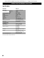
Specifications
4
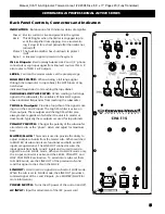
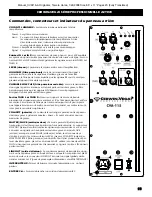
Back Panel Controls, Connectors and Indicators
5
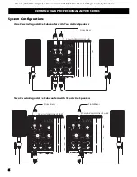
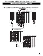
System Configurations
6
Contact Information
Back Cover
Important Safety Instructions
1. Read and keep these instructions.
2. Heed all warnings and follow instructions.
3. Do not use this apparatus near water.
4. Clean only with a dry cloth.
5. Do not block any ventilation openings.
6. Do not install near any heat sources such as radiators, heat registers,
stoves, or other apparatus that produce heat.
7. This product is equipped with a polarized alternating-current line plug (a plug
having one blade wider than the other). This plug will fit into the power out-
let only one way. This is a safety feature. If you are unable to insert the plug
fully into the outlet, try reversing the plug. If the plug should still fail to fit,
contact an electrician to replace your outlet. The plug is configured this way
for your safety.
8. Protect the power cord from being pinched, particularly at plugs,
convenience receptacles, and the point where they exit.
9. Only use attachments / accessories specified by the
manufacturer.
10. Use only with a cart, stand, bracket, or table specified
by the manufacturer or sold with the apparatus. When
a cart is used, use caution when moving the cart /app-
ratus combination to avoid injury from tip-over.
11. Unplug this apparatus during lightning storms or
when unused for long periods of time.
12. Refer all servicing to qualified service personnel.
Servicing is required when a liquid has been spilled, or objects have fallen, into
the apparatus; the apparatus has been exposed to rain or moisture; the appar-
tus does not operate properly or has been dropped; or if it has been damaged
in any other way.
13. To reduce the risk of fire or electric shock, do not expose this appa-
ratus to rain or moisture.
14. The apparatus shall be connected to a main socket outlet with a protective
connection.
a.) Mains plug is used as the disconnect device. It shall remain readily
operable and should not be obstructed during intended use.
b.) Ensure that the apparatus is not exposed to dripping or splashing and that
no objects filled with liquids, such a vases, are placed on the apparatus.
Explanation of Graphic Symbols
The exclamation point in a triangle is
intended to alert you to the presence of
important operating and maintenance
(servicing) instructions in this document.
The lightning flash with the arrowhead
symbol, within an equilateral triangle, is to
alert you to the presence of insulated
“dangerous voltage” within the product’s
enclosure that may be of sufficient
enough magnitude to constitute a risk of
electric shock.
CAUTION: TO REDUCE THE RISK OF
ELECTRONIC SHOCK - DO NOT REMOVE
COVER. NO USER SERVICEABLE PARTS
INSIDE. REFER SERVICING TO QUALIFIED
PERSONNEL.
The IEC fuse symbol pictured at the left
represents an approved user replaceable
fuse. When replacing a fuse, make sure
to replace with only the correct type and
rating.
Introduction
Congratulations! Welcome to the Cerwin-Vega! family. You've made a great move by joining a growing group of
audio professionals who have turned to Cerwin-Vega! for the most advanced audio reproduction systems avail-
able. All Cerwin-Vega! systems are thoroughly tested to ensure that they meet or exceed our performance specifi-
cations. Backed by the best service in the industry, Cerwin-Vega! is dedicated to quality and reliability. What this all
means to you is that your system will rock! For a complete overview of Cerwin-Vega! products and services, check
us out at
www.cerwin-vega.com
.
CAUTION
RISK OF ELECTRIC SHOCK
DO NOT OPEN!
DO NOT EXPOSE
TO RAIN OR MOISTURE
#?!*@
Important Symbols and Safety Instructions
English
Summary of Contents for CVA-115
Page 1: ...ACTIVE SUBWOOFER CVA 115...
Page 20: ...LITP000034 REV A...