System Manual
©
2019
Cervis, Inc.
7
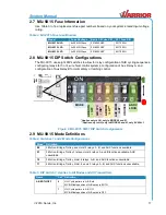
Table 1. MU-9X15 Diagnostic LEDs
LED
Name
LED State
Description
1
Health
Blinking
Unit OK, normal processor operation
2
TX (Transmit)
Fast Blinking
Indicates RF Messages sent to handheld
3
RF 3.3 V
Steady Lit
Indicates RF 3.3 V bus OK
4
RX (Receive)
Fast Blinking
Indicates RF Messages received from handheld
5
System 12 V
Steady Lit
Indicates System 12 V bus OK
6
Logic 3.3 V
Steady Lit
Indicates Logic 3.3 V bus OK
7
System 3.3 V
Steady Lit
Indicates System 3.3 V bus OK
LED per
Relay (16)
Relay State
Steady Lit
Relay Active
Each of the 16 relays has its own LED. When commanded, the relay LED illuminates.
2.3
MU-9X15 Mounting
Caution!
Disable the machine on which the receiver is to be
attached before installation to avoid injury.
Use the configuration diagrams supplied by Cervis, Inc. to guide you in mounting the receiver
and connecting your wire harness. Receiver mounting is left much to your discretion with the
following guidelines:
•
Make sure that the configuration diagrams supplied with the system are available. Keep
them where they can be easily accessed when needed.
•
Mount the receiver away from any intense radio or electric disturbance sources.
•
Mount the receiver where there is enough room to make wiring harness terminations.
•
Make sure the mount is secure.
•
The external antenna must be connected only as recommended by Cervis, Inc. with parts
recommended by Cervis, Inc.
Under no circumstances can a signal amplifier be used.
•
Mount the device so that the unit antenna is in the operator
’s view. Apply an antenna
extension cable if needed. Cervis, Inc. optional extension cables are 3-ft. (J5-07), 10-ft.
(J5-02), or 25-ft. (J5-13). See Figure 6.

