


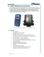


SmaRT 902 Remote Control System
U007.0-SmaRT902_system-R
4
5. When LINK flashes yellow, release the two buttons. The RX button flash-
es red allowing two (2) seconds for you to make the next button press.
9
Note: If the next button press is not performed within the two second interval that RX
flashes red, the procedure is aborted and must be started anew to establish
the Association.
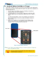
6. Press and hold the Associate button (See below). The RX extinguishes,
the TX lights steady green, and the LINK LED lights steady yellow.
7. Apply power to the base unit while continuing to hold the Associate but-
ton.
The base unit and handheld begin to Associate and establish a communications link.
Once the Association is complete, the yellow LINK led extinguishes, the RX begins
flashing red, and the TX lights steady green and remains so until the button is released.
8. Release the Associate button. The RX LED extinguishes, the TX LED
flashes green for a brief time, and then it too extinguishes.
The SmaRT 902 System is ready for use with that particular handheld remote.
Figure 5. Handheld PTO Buttons
1.4.2 Disassociate Handheld to Base Unit Procedure
In some circumstances it may become necessary to disassociate a handheld that is
linked to a base unit. The procedure to Disassociate handhelds from the base unit is
almost identical to the Associate procedure except the Disassociate button is used and
held throughout the process.
9
Note: The following procedure will Disassociate all remotes linked to the base unit.
CAUTION
Completion of the following steps will Disassociate all handheld
remote links previously established. It will be necessary to per-
form the Associate Procedure (1.4.1 above) using each handheld
to re-establish communication links with the base unit.
Yellow while linking
ASSOCIATE
TO BASE UNIT
DISASSOCIATE
FROM BASE UNIT


