


34
MB Pool & spa heater
185, 265 & 405 Models
CONTROL FAULT DIAGNOSIS
Before commencing a diagnosis it is recommended that
you familiarise yourself with the functions of the Controls.
These are detailed in the
User's Operating Instruc-
tions Page 2
. The Control will diagnose and display
most of its own faults.
Self Check
The Control does a full self check during power up. It
also briefl y lights all the LEDs and the Temperature Dis-
play so they can be checked for operation.
Pool Heating
The Control will try and fi re the Heater provided that:
1. There is a Mains supply
2. The Heater is switched on
3. The Set temperature is above the Actual
temperature.
4. The safety switches are all satisfi ed.
This will be indicated by the Green LED next to the dis-
play. On for fi ring, Off for no demand and Flashing for up
to temperature.
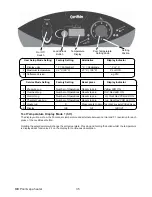
Fault Indicators
There four LED indicators on the Control. Two on the
Front Panel, Red for the Manual Overheat, Yellow for the
Pressure Switch.
Two on the board behind the display, one for the Rollout
or Thermal Fuse and one for the Hi-Limit Thermostat.
If any one of the safety switches open the associated
LED will light.
NB
if more than one opens only one LED
will light, the fi rst in the chain.
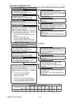
Displayed Faults
The Control board detects and displays certain faults,
the display alternates between the two codes.
Logs
The Control keeps a log of the number of times
the Pressure Switch, Manual Overheat, Hi-Limit
and Thermal Fuse (Rollout) fail. These can be
examined and reset to zero in Setup Mode. The
Temperature Displayed units and the Maximum
Temperature can also be checked and viewed in
Setup Mode.
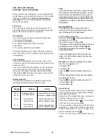
User Setup Mode
The following must be carried out within 5
seconds of turning on the Mains supply, this is
when the display is fully illuminated.
Turn the Mains supply ON.
Press and hold the Lock/Unlock Button until
the display stops fl ashing.
The Control is now in Setup Mode.
The display will show additional data as the Pool
Temperature Knob is rotated.
See Page 35
The settings are altered by pressing the
Lock/Unlock Button.
To leave Setup Mode and retain the new set-
tinngs, turn off the Mains supply for a few sec-
onds at any time.
Example
. To change the Display from Fahren-
heit (
°F
) to Centigrade (
°C
)
Turn Mains OFF
Turn Mains ON
Press the Lock/Unlock button within 5 sec-
onds
Turn the Temperature Control Knob to postion 1,
the display will show
°F
Press the Lock/Unlock button to alter to
°C.
Turn the Mains OFF
Turn the Mains ON
Service Mode
This is a special mode used to set the operation
of the Control and to investigate fault conditions.
Enter User Setup Mode.
Rotate Pool Thermostat knob fully clockwise to
show the software version number.
Press the Lock/Reset Button for 3 seconds.
The control is now in Service Mode.
It is now possible to change some of the Control’s
parameters. To show them, rotate the Pool Ther-
mostat Potentiometer. To zero or change them,
press the Reset/Lock button
To exit, turn the Panel Switch off then back on
again.
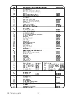
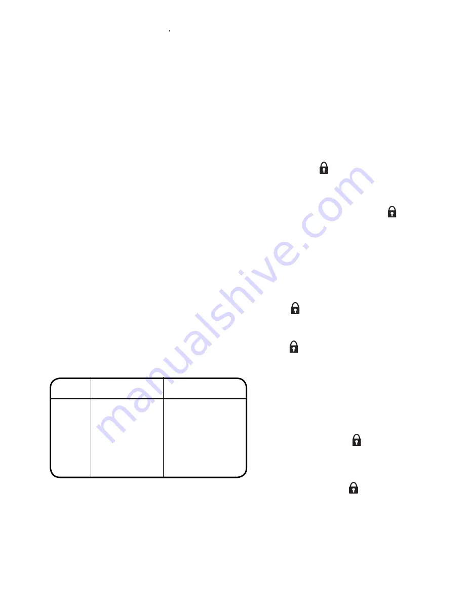
Power off then on. If not
corrected, replace board
Check connections, if
correct, replace sensor
Check connections, if
correct, replace sensor
Pot Open circuit
Pot Short circuit
Pool sensor
Open Circuit
Pool sensor
Short circuit
Err / 4
Err / 5
P / oc
P / cc
Display
Reason
Action