background image

Radikal Gasser

Page 8

HEAD ASSEMBLY (LT VERSION)

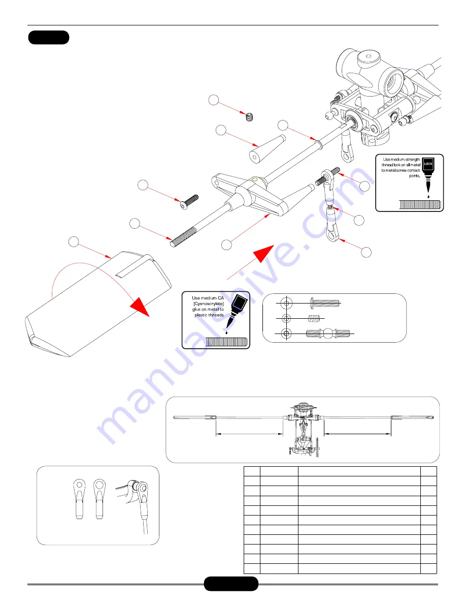
Pushrod assembly (parts 2 through 4) is already assembled but check that the length is 
actually 43mm (center to center). As the pushrods are built and installed they should be 
checked for tightness. Press one ball link onto each double studded steel ball, making sure 
that pressure is applied from the side of the ball link with circle mark. While holding one 
flybar control arm, apply a small amount of slow cyanoacry-
late glue and thread one end of the double studded steel ball 
into each standoff. When it becomes difficult to turn with fin-
gers, apply slow CA to the threads and start screwing in the 
tapered control arm stand-off on the other end of the ball.  
Slide and center the flybar through the head assembly. Care-
fully look at the flybar control arm assemblies from the previ-
ous step and notice that when installed correctly, the secur-
ing set screw is on top. Insert one M4x6x0.5 micro washer 
#CNLR1006  against  each  bearing  then  slide  the  control 
arm halves onto each side, so that 
they match together and the set 
screw remains on top. Insert one 
M3x12 button head socket screw 
to  secure  the  opposite  standoff. 
Hold  the  tapered  standoff  using 
pliers  while  tightening  the  screw 
as  the  rotor  head  rotates  clock-
wise.

Loosely tighten the M4x5 set screws into the round aluminum inserts aligned with the flat spots on the flybar. Tighten both set screws, one 
at a time using Medium threadlock. Make a pencil mark 5mm past the threads on both ends of the flybar. Thread the flybar paddles onto the 
flybar until the mark is reached and align the paddles parallel. Again using the ruler, rotate one paddle or the other to get equal distances while 
remembering the leading edge of the paddles turn clockwise.

NOTICE SIZE OF HOLES ON BALL LINKS

THE SIDE WITH THE SMALLER HOLE 
SHOULD FACE OUTWARDS

Make sure the distance on

 both sides are equal

Make sure the distance on

 both sides are equal

1

4

5

7

6

8

9

10

3

2

CNM3X12BHCS

CNM4X5SS

2

4

Seesaw Tie Bars(

稳定翼控制臂

)

2

2

Pushkod Set(

拉杆

)

Ball Link Set(26 Long,4 Short)(

球头连接头

)

Washer 4x6x0.5(

平面垫片

)

M3 Two-tooth Screw Ball(

M3球头双牙螺丝

)

2

No.

Description

Qty

1

2

3

4

5

Part #

6

M4x5 Socket Head Set Screw

(

无头内六角螺丝

)

7

8

9

10

Seesaw Tie Bars(

平衡杆控制臂

)

M3x12 Button Head Cap Screws(

圆头内六角螺丝

)

Flybar Paddles(

平衡片

)

HI3167C

HI6145

Hw6192

HI3167C

CNLR1006

CNM4X5SS

HI3167C

CNM3X12BHCS

HI6179B

2

2

2

2

1

(平衡杆)

HW6173A

4mm FLYBAR 500mm

BAG 1

CA

HW3176C

Summary of Contents for Radikal G20

Page 1: ...ess to spark plug Triple bearing supported blade grips and tail blade grips Machined center dual ball bearing swashplate for 120 degree CCPM Adjustable bell hiller ratio allows tuning for preferred cyclic response HD Tunable flight characteristics for stability or speed Length 1366mm Height 381mm Width 260mm Main rotor diameter 1435mm Tail rotor diameter 262mm Main rotor blades 600mm 640mm Tail ro...

Page 2: ...illing and packing of each bag however mistakes do happen If there is a parts shortage or missing hardware please contact us at General Guidelines Apply thread lock to all metal to metal thread contact points Do not apply CA cyanoacrylate glue or thread lock to ny lock nuts metal nuts with plastic inserts Diagrams indicated by bounding boxes for screws bearings etc are illustrated at a 1 to 1 rati...

Page 3: ... right to change or modify this warranty without notice and disclaims all other warranties express or implied b Limitations CENTURY HELICOPTER PRODUCT MAKES NO WARRANTY OR REPRESENTATION EXPRESS OR IMPLIED ABOUT NON INFRINGEMENT MERCHANTABILITY OR FITNESS FOR A PARTICULAR PURPOSE OF THE PRODUCT THE PURCHASER ACKNOWLEDG ES THAT THEY ALONE HAVE DETERMINED THAT THE PRODUCT WILL SUITABLY MEET THE REQU...

Page 4: ... place with the other side for spectators Only personnel involved with flying the aircraft are allowed at or in front of the flight line Intentional flying behind the flight line is prohibited 4 I will operate my model using only radio control frequencies currently allowed by the Federal Communications Commission Only properly licensed Amateurs are authorized to operate equipment on Amateur Band f...

Page 5: ...l spacer and carefully apply Medium threadlock to the exposed threads and insert into the right side of the head block Do not overtighten Repeat for the second sub assembly Once complete apply a small amount of slow cyanoacrylate glue and insert one CNLR1020 special long thread ball into each offset plate to com plete the assembly Do not open all the bags prior to starting assembly Open the bags s...

Page 6: ...second sub assembly Once complete apply a small amount of slow cyanoacrylate glue and insert one CNLR1020 special long thread ball into each offset plate to complete the assembly Do not open all the bags prior to starting assembly Open the bags step by step as you go through the instruction manual The components are bagged to make assembly easier The next few pages will pertain to the assembly of ...

Page 7: ...ff using pliers while tight ening the screw as the rotor head rotates clockwise Apply a small amount of cya noacrylate glue to the special long thread ball All ball links are molded to be in stalled in only one direction Look carefully at the hole for the ball as that side is 1mm larger Loosely tighten the M4x5 set screws into the round aluminum inserts aligned with the flat spots on the flybar Ti...

Page 8: ...x12 button head socket screw to secure the opposite standoff Hold the tapered standoff using pliers while tightening the screw as the rotor head rotates clock wise Loosely tighten the M4x5 set screws into the round aluminum inserts aligned with the flat spots on the flybar Tighten both set screws one at a time using Medium threadlock Make a pencil mark 5mm past the threads on both ends of the flyb...

Page 9: ...rence Use the center hole for sport flying Make two assemblies Using an available M3 screw carefully form the threads in the blade grip arm Slide the M3x18 special socket shoulder screw through the bell mixer arm from the flat side add one M3x5x3 spacer and apply a drop of Slow Cyanoacrylate glue or Epoxy glue to the end of the threads before installing into the blade grip Tight en the bolt until ...

Page 10: ...E GRIP SIDE PROFILE BLADE GRIP RECESSED CREVICE FACES MAIN SHAFT THRUST BEARING INSTALLATION GUIDE GROOVES INSIDE 1 3 2 5 4 6 7 8 9 11 12 13 10 14 15 3 9x13x1 3x5x3 CNBB1370T CNM5LOCK CNM3x14BHSC M3 CNLR1014 M3 CNLR1016A CNBB0730 CNBB1360 3x5x0 5 2 M5 Locknut M5防松螺母 CNM5LOCK 2 CNBB1370T Thrust Ball Bearing 止推轴承 7x13x4 5 4 8 CNBB1370 Bearing 滚珠轴承 7x13x4 Washer 垫片 9x13x1 2 Main Rotor Blade Grip 主桨夹片...

Page 11: ... main shaft do not over torque Position the washout guide against the collar and align one hole to the vertical slot in the rotor head Apply Medium threadlock to the M3x4 set screws and evenly tighten set screws in place 1 2 3 4 5 6 Do not apply CA or thread lock to lock nut M3x4 M4x22 M2 5x8 M4防松螺母 BAG 1 Do not over tighten No Description Qty 1 2 3 4 5 6 Part 1 2 1 1 1 Aluminum Washout Guide 剪型臂导...

Page 12: ...t the main shaft do not over torque Position the washout guide against the collar and align one hole to the vertical slot in the rotor head Apply Medium threadlock to the M3x4 set screws and evenly tighten set screws in place CNM2 5x8CS CNM3LOCK CNM3x18CS CNM3x4SS 1 2 3 4 5 6 HW3053B 2 CNM2 5x8CS Cap Screw 杯头内六角螺丝 M2 5x8 1 M3 Locknut 防松螺母 CNM3LOCK 1 Cap Screw 杯头内六角螺丝 M3x18 CNM3x18CS 1 Main Shaft 主...

Page 13: ...readlock Install three long steel balls on the outer arms using Slow Cyanoacrylate glue 10 11 12 BAG 1 M10x12x5 HI3152C M3 L 7 8MM CNLR1014 CNBB0730 M3x5x0 5 CNLR1003 CNM3x16BHCS M3 L 18MM Ø2x12 No Description Qty 1 2 3 4 5 Part 6 7 8 9 10 11 12 CNLR1014 CNM3x16BHCS HI3152A HI3152C CNLR1003 HW6146C HI3152A CNLR1014 CNLR1021 2 摆臂 2 3x5x3 Bellcrank Spacer 铜套 2 Washout Set 控制臂固定座 3x5x0 5 Micro Washer...

Page 14: ...ct Please make sure to check it prior to installation 1 2 3 4 8 7 5 9 6 11 10 12 Comes pre assembled BAG 1 No Description Qty 1 2 3 4 5 Part 6 7 8 9 10 11 12 CNLR1014 CNM3x16BHCS HI3152A HI3152C CNLR1003 HW6146C HI3152A CNLR1014 CNLR1021 2 2 3x5x3 Bellcrank Spacer 铜套 2 Washout Set 控制臂固定座 3x5x0 5 Micro Washer 垫圈 2 4 2 1 2 2 4 2 CNBB0730 HI3152A Radikal Swashplate 十字盘 1 M3 Ball Link M3球头螺丝 3x7x3 Bea...

Page 15: ...HE SIDE WITH THE SMALLER HOLE SHOULD FACE OUTWARDS DRAWN TO A SCALE OF 1 TO 1 YOU CAN MATCH YOUR LINKS UP TO THIS PAGE FOR PROPER MEA SUREMENTS A C B 1 2 3 4 5 A B C 43 25 14 75 No Description Qty 1 2 3 4 5 Part 2 4 8 2 2 Ball Link Set 26 Long 4 Short 球头连接杆 HI6145 HI6145 HW6192A Pushrod Set 连杆 HW6192A HW6192A Ball Link Set 26 Long 4 Short 球头连接杆 Pushrod Set 连杆 Pushrod Set 连杆 BAG 1 25 5 95 ...

Page 16: ...ON BALL LINKS THE SIDE WITH THE SMALLER HOLE SHOULD FACE OUTWARDS 94 43 25 25 14 1 2 3 5 4 A B C 75 HI6145 Ball Link 塑胶球头连接头 HW6192 Pushrod 连杆 L 25MM 2 HW3192A Pushrod 连杆 L 80MM HW6192 Pushrod 连杆 L 14MM 2 HI6145 Short Ball Link 短塑胶球头连接头 8 2 4 No Description Qty 1 2 3 4 5 Part DRAWN TO A SCALE OF 1 TO 1 YOU CAN MATCH YOUR LINKS UP TO THIS PAGE FOR PROPER MEA SUREMENTS BAG 1 ...

Page 17: ... HI6032G HI6113 No Description Qty 1 2 3 4 6 7 5 8 9 10 12 11 Part Flush Head Cap Screws 斜头内六角螺丝 M3x10 1 2 2 Lower Main Shaft Bearing Block 主轴下轴承座 1 2 1 Pin 插销 Ø2x24 HI6032G 1 A Arm A型控制臂 1 1 HI6032G A Arm Base A 型控制臂座 1 1 Flush Head Cap Screws 斜头内六角螺丝 M2 5x6 CNM2 5x6FHCS 2 This bearing is already pressed into the bearing block 3 If you have carbon fiber frames just add a C to the end of the frame...

Page 18: ... mounting onto the skeletal support frame assembly Once done install the M3x8 button head cap screws as shown Apply medium threadlock to all the screws If you have carbon fiber frames just add a C to the end of the frame part number 2 3 4 1 5 6 Main Frames 左右后侧板 Button Head Cap Screw 圆头内六角螺丝 M3x8 CNM3x8BHCS Bearing 滚珠轴承 10x19x5 CNBB1019 HI6116L HW6042GU No Description Qty 1 2 3 4 Part 5 6 Bearing ...

Page 19: ... the M3 5x24 Phillips screw so that you barely grab the end of the small cap 4 Once you insert the fuel tubing assembly into the tank it will be very dif ficult to get this small cap out if you happen to drop it within the fuel tank Making sure you still have the small cap 4 attached to the fuel tubing assembly push the fuel tubing assembly into the tank and start tightening the Phillips screw Thi...

Page 20: ...3x8BHCS CNM3x25BHCS CNLR1014 CNBB0730 3x8x3 5 CNM3x12BHCS CNBB812F CA When installing the elevator bellcrank make sure to apply medium CA to the M3x12 button head cap screw Assemble the aileron bellcranks by first pressing in the 3x7x3 bearing followed by the 3x5x7 5 spacer In stall the remaining bearing along with the metal balls It is easier to thread the M3 linkage balls into the plastic bell c...

Page 21: ...s Apply medium threadlock to the two M4x4 set screws and tighten in place Clean the top of the pinion gear and the inside surfaces of both the upper and lower bearings inside the clutch shaft bearing block using alcohol Apply a small amount of Red threadlock to the top edge of the clutch gear where it will contact the bearing Press the bearing block in place firmly seating the bearing against the ...

Page 22: ...d clutch assembly After you have removed the hub remove the bot tom plate and flush head cap screws Set these aside as you will not be needing them for the rest of the build First undo the nut and remove the propeller washer Screw down the original nut onto the stud followed by the locknut Install the supplied 13mm locknut and tighten down onto the shaft Tighten down on the top lock nut while appl...

Page 23: ...e a pull start for the first start of the day Afterwards using a heavy duty electric starter is possible CNLR1018 CNM6x16CS 6 5x13x1 CNM2 5x8CS CNM4x10FHCS CNM3x4SS 6 5x13x1 CNM3x6FHCS 1 2 3 4 5 6 7 11 13 12 17 14 16 15 8 9 10 HI6020G HW6011G CNM6 5X13FW HW6118W ZENE20EIN OT INCLUDED No Description Qty 1 2 3 4 6 7 5 8 9 10 Part 11 12 13 14 HW6011GS 15 16 17 Plastic Cooling Shroud 风扇罩 1 CN2263K 3 A...

Page 24: ...头内六角螺丝 M2 5x8 CNM2 5x8CS 6 CNLR1003 Sensor Adaptor Board 感应器固定板 1 1 2 Sensor 感应器 Copper Sleeve 铜套 2 5x4x4 2 Flush Head Cap Screws 斜头内六角螺丝 M4x10 CNM4x10FHCS 2 2 BAG 2 Mount the plate onto the engine first and tighten the M4x10 Flush Head Cap Screws After you have installed the plate then install the sensor The sensor can be adjusted slightly to advance or retard timing ...

Page 25: ...座 2 Flush Head Cap Screws 斜头内六角螺丝 M2 5x6 CNM2 5x6FHCS 8 BAG 3 Start by installing the four M2 5x6 flush head cap screws into the lower electronics tray by using medium threadlock Use the M3x30 Phillips tapping screws to mount the canopy hook Do not overtighten this as you can strip the plastic Next apply medium threadlock to the remaining four M2 5x6 flush head cap screws and install them into the...

Page 26: ...en fitting the electronics trays that you have a com plete mating with the upper side frames If the keys do not fit into the slots on the upper side frames and you tighten down on the screws your frame will be crooked Apply medium threadlock to the eight M3x8 button head cap screws and tighten down If you have carbon fiber frames just add a C to the end of the frame part number ...

Page 27: ...头内六角螺丝 M4x10 CNM4x10CS No Description Qty 1 2 Part 6 4 MOUNTING MOTOR BAG 2 Loosely fit the CNM4X10 cap screws that hold the engine on the plate Then line up the bearing assembly in the upper portion of the frames Keep this loose for now until you are ready to mesh the pinion gear with the main gear 2 1 ...

Page 28: ...G 2 When mounting the front frames to the rear frames make sure the keyed split matches up properly prior to tightening the eight M3x8 button head cap screws This is very important as you can warp the frames if it s not set in place when tightening down Prior to installing the eight M3x8 button head cap screws be sure to use medium threadlock ...

Page 29: ... the landing skids position the landing struts on the skids so that they match up with the mounting positions on the frames Place the washers onto the M3x16 cap screws and then apply medium threadlock Install the screws through the landing struts and tighten onto the frames Turn the landing skids so that the curve towards the front is facing straight up Make sure you have approximately 28mm of ski...

Page 30: ...m mend a very light oil The oil MUST NOT attack break down plastic as this could damage the cage in the one way bearing Prior to applying oil make sure to clean the roller bear ings with a cotton swab making sure there is no debris in the bearings Apply medium threadlock to the four M3x6 flush head cap screws and install through the tail drive gear tightening onto the driven tail hub Apply medium ...

Page 31: ...assembly into the frames Insert the main shaft with head assembly through the bear ing blocks while lining up the thrust bearing and mast stopper while go ing through the Main Gear assembly Line up the whole in the Main Shaft with the hole on the Driven Tail Hub With the help of needle nose pliers or hemostats place the Pin 5 through while making sure you have it going through the Main Shaft Insta...

Page 32: ...mes just add a C to the end of the frame part number Part Copper Rivet 铜铆钉 Anti Vibration Pad 防震胶垫 2 Tail Servo Mount 尾翼伺服机座 2 Cap Screw 杯头内六角螺丝 M3x10 CNM3x10CS 2 Servo 伺服机 4 Self Tapping Screws 尖尾自攻螺丝 M2 3x12 2 Servo Mounting Plate 伺服机固定板 CNM2 3x12ST Steel Ball 2mm Thread m2 球头螺丝 CNLR1013 1 M2 Hex Nuts m2六角螺母 2 CNLR1018 1 Adjustable Tail Guides 尾拉杆固定座 1 1 Horizontal Fin Mount 水平翼固定座 Button Head S...

Page 33: ...HI6078B HI6078P HI6078P HI6631 No Description Qty 1 2 3 4 6 7 5 8 9 10 12 13 11 14 15 17 18 16 19 20 21 22 23 24 Set Screw 无头内六角螺丝 M3x4 CNM3x4SS Part BAG 4 When pressing the bearing retainers into the tail gear box plate make sure you are pressing it into the correct side The left and right side are different If you do not do this it will be difficult to remove this pieces once it s pressed in Whe...

Page 34: ... pre assembled Starting with the tail rotor assembly press the 4x10x4 11 bearing into the tail blade grip Grease the thrust bearings prior to installation Making sure the open ball end is facing the tail hub place the thrust bearing assembly into the tail blade grip followed by the 3x5x0 5 micro washer Install the 3x9x2 5 4 bearing and then tighten the assembly with the M3 locknut Slide one M3x18 ...

Page 35: ...AG 4 You may notice the boom and the tail transmission case is scuffed This is done during the manu facturing process to ensure a proper grip HELICOPTER NOSE TAIL OUTPUT SHAFT TRANSMISSION CASE When orienting the belt the front trans mission pulley as viewed from the top should be turning counter clockwise When the belt is twisted as shown below the rear tail pulley should turn counter clockwise w...

Page 36: ...sion gear is properly meshed with the tail drive gear If you are unsure about proper gear mesh use a strip of paper slightly taller than the tail drive gear and pass it between the gears as you spin the tail drive gear As the paper passes through from one side of the frames to the other a nice zig zagged pattern should develop If it is a very faint zig zag pattern or no pattern ap pears the gear m...

Page 37: ...rew drive so as to not strip the head of the Phillips tapping screws BOLTS BAG 1 2 3 4 6 9 10 11 NOT INCLUDED 7 8 5 Phillips Screw 十字螺丝 M2x6 10 CNM2x6PH 3 Pitch Compensators 伺服机控制臂 6 M3 Linkage Ball 球头螺丝 CNLR1014 16 Self Tapping Screws 尖尾自攻螺丝 M2 3x12 CNM2 3x12ST 8 Servo Mounting Plate 伺服机固定板 4 Servo 伺服机 1 Metal Servo Arm 金属伺服机控制臂 CN2288 Steel Ball 2mm Thread M2 球头螺丝 CNLR1013 1 Servo Mount Tabs 伺服机...

Page 38: ...4 HW6192D Pushrod 连杆 L 85MM 2 2 Pushrod 连杆 L 55MM HW6192D No Description Qty 1 2 3 4 5 Part 72 2 55 93 6 105 106 85 47 8 25 1 2 3 4 5 76 4 BOLTS BAG NOTICE SIZE OF HOLES ON BALL LINKS THE SIDE WITH THE SMALLER HOLE SHOULD FACE OUTWARDS HEL PFUL TOOL PART CN2255 CONTROL ROD SETUP GAUGE PART CN2219A BALL LINK EASY DRIVER HELPFUL TOOL ...

Page 39: ...e engine to operating temperatures and then re torque the M5 bolts holding the muffler in place 1 2 INCLUDED If you purchased a Zenoah G20 en gine the engine package should in clude the stock black box muffler This muffler can be used however if installed without any modifications it is VERY DANGEROUS as the muffler tip is pointed directly at the fuel tank DO NOT USE IT THIS WAY If you choose to u...

Page 40: ...eiver Battery 电池 Gyro Isolation Foam 防震垫片 Gyro 佗螺仪 NOT INCLUDED NOT INCLUDED NOT INCLUDED NOT INCLUDED NOT INCLUDED NOT INCLUDED No Description Qty 1 2 3 4 6 5 Part 1 1 1 1 1 On Off Switch 开关 The electronics configuration is shown as an example of how to mount the electronics It is not necessary to mount your electronics this way ...

Page 41: ...mmets onto the canopy standoffs you can use a dab of oil Prior to making the holes for the canopy chin mount you should mount your canopy to the mechanics making sure any linkages servos etc are not touching the canopy It may be nec essary to cut the canopy to avoid binding these linkages Also make sure your muffler is not touching the canopy as the canopy will melt It will be necessary to cut the...

Page 42: ... roots are glued with a medium CA or epoxy Make sure you re glueing onto the wooden part of the blade and not directly onto plastic covering of the blades If the plastic covering is in place and con tacting the plastic blade roots make sure to cut this away prior to glueing It is recommended to fly this model with carbon fiber blades however when flying with wooden blades make sure to keep the hea...

Page 43: ...Radikal Gasser Page 43 PERSONAL BUILD NOTES ...

Reviews: