background image

Page 14

Installation and Operation Manual - FW3500

ENGLISH

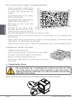
Here are some facts to consider in estimating drying time:


− Firewood bought from a dealer is rarely 

dry enough to burn, so it is advisable 
to buy the wood in spring and dry it 
yourself;


− Drying happens faster in dry weather 

than in a damp climate;


− Drying happens faster in warm summer 

weather than in winter weather;


− Split pieces dry more quickly than 

unsplit rounds;


− Softwoods like pine, spruce, poplar, 

and aspen take less time to dry than 
hardwoods. They can be dry enough to 
burn after being stacked to air dry only for the summer months;


− Hardwoods like oak, maple and ash can take one, or even two years to dry fully, especially if the 

pieces are big;


− Firewood dries more quickly when stacked outside in a location exposed to sun and wind; it takes 

much longer to dry when stacked in a wood shed;


− Firewood with a moisture content of 15% to 20% will allow the stove to reach its highest efficiency.

Firewood is dry enough to burn when:


− Cracks form at the end of logs;


− The wood turns from white or cream colored to grey or yellow;


− Two pieces of wood struck together sounds hollow;


− The face of a fresh cut feels warm and dry;


− The moisture content read by a moisture meter is between 

15% to 20%. 

4.  Operating the Stove

Before using the stove, install the coil handles located in the user manual kit.

This wood heater has a manufacturer-set minimum low burn rate that 
must not be altered. It is against federal regulations to alter this setting or 
otherwise operate this wood heater in a manner inconsistent with operating 
instructions in this manual.

Summary of Contents for CB00024

Page 1: ... FOLLOW THESE INSTRUCTIONS COULD RESULT IN PROPERTY DAMAGE BODILY INJURY OR EVEN DEATH READ AND KEEP THIS MANUAL FOR REFERENCE 46204A 2020 09 09 Installation and Operation Manual FW3500 CB00024 model MOBILE HOME Safety tested according to ULC S627 UL 1482 and UL 737 standards by an accredited laboratory ENGLISH US Environmental Protection Agency phase II certified wood stove compliant with 2020 co...

Page 2: ......

Page 3: ...tove and the chimney that it is connected to It is also highly recommended to inform your home insurance company Please read this entire manual before installing and using this stove A primary alternative heat source should be available in the home This heating unit may serve as a supplementary heat source The manufacturer cannot be responsible for additional heating costs associated with the use ...

Page 4: ...ying Time 13 4 Operating the Stove 14 4 1 The Use of a Fire Screen 15 4 2 Blower Operation 15 5 Burning Wood Efficiently 16 5 1 First Use 16 5 2 Lighting Fires 16 5 3 Combustion Cycles 17 5 4 Rekindling a Fire 18 5 5 Removing Ashes 18 5 6 Air Intake Control 19 5 7 Fire Types 19 6 Maintenance 21 6 1 Cleaning and Painting 21 6 2 Refractory Materials and Baffle 21 6 3 Glass Door 21 6 4 Door 22 6 5 Ex...

Page 5: ... 35 9 3 Chimney Location 35 9 4 Supply of Combustion Air 36 9 5 Chimney Connector 37 Appendix 1 Optional Fresh Air Intake Kit Installation 39 Appendix 2 Optional Fire Screen Installation 40 Appendix 3 Optional Blower Installation 41 Appendix 4 Optional Thermodisc Installation 42 Appendix 5 Air Tubes and Baffle Installation 43 Appendix 6 Mobile Home Installation 45 Appendix 7 Optional ash pan insta...

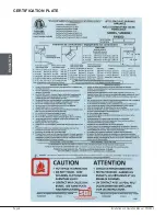
Page 6: ...Page 6 Installation and Operation Manual FW3500 ENGLISH CERTIFICATION PLATE ...

Page 7: ...ore opening the loading door NEVER USE GASOLINE LANTERN FUEL NAPHTHA FUEL OIL MOTOR OIL KEROSENE CHARCOAL LIGHTER FLUID OR SIMILAR LIQUIDS OR AEROSOLS TO START A FIRE IN THIS STOVE KEEP ALL SUCH LIQUIDS OR AEROSOLS WELL AWAY FROM THE STOVE WHILE IT IS IN USE Do not store fuel within heater minimum installation clearances Burn only seasoned natural firewood This appliance should always be maintaine...

Page 8: ...d heating area and maximum burn time may vary subject to location in home chimney draft heat loss factors climate fuel type and other variables The recommended heated area for a given appliance is defined by the manufacturer as its capacity to maintain a minimum acceptable temperature in the designated area in case of a power failure 2 The maximum heat output dry cordwood is based on a loading den...

Page 9: ...Safety ULC S627 10 North south ends of the logs visible East west sides of the logs visible 11 Mobile homes Canada or manufactured homes USA The US Department of Housing and Urban Development describes manufactured homes better known as mobile homes as follows buildings built on fixed wheels and those transported on temporary wheels axles and set on a permanent foundation In Canada a mobile home i...

Page 10: ...view Figure 2 Front view SECTION A A 12 7 8 326mm 20 1 8 510mm 5 16 8mm 3 16 5mm 17 7 8 454mm Figure 3 Side view Figure 4 Combustion chamber side view 22 7 8 581mm 9 7 8 249mm 19 483mm Figure 5 Combustion chamber front view Figure 6 Door opening 16 5 8 422mm 11 3 4 299mm 25 3 4 654mm 24 610mm 14 3 8 366mm 3 7 28 1 8 714mm 9 230mm O 6 153mm 5 8 mm 11 3 4 299mm 3 4 4mm 24 610mm 24 1 4 615mm 14 3 8 3...

Page 11: ...mperature glass Ceramic glass cannot be recycled in the same way as normal glass so it should not be disposed of with regular household products Disposal at a waste management center is recommended 2 5 Zone Heating This stove is a space heater which means it is intended to heat the area it is installed in as well as spaces that connect to that area although to a lower temperature This is called zo...

Page 12: ...ed is in the correct moisture content range of 15 to 20 Refer to the following section of suggestions on preparing fuelwood and judging its moisture 3 Fuel Good firewood has been cut to the correct length for the stove split to a range of sizes and stacked in the open until its moisture content is down to 15 to 20 DO NOT BURN GARBAGE LAWN CLIPPINGS OR YARD WASTE MATERIALS CONTAINING RUBBER INCLUDI...

Page 13: ... loading the stove very difficult The most common standard length of firewood is 16 400 mm 3 3 Piece Size Firewood dries more quickly when it is split Large unsplit rounds can take years to dry enough to burn Even when dried unsplit logs are difficult to ignite because they don t have the sharp edges where the flames first catch Wood should be split to a range of sizes from about 3 to 6 75 mm to 1...

Page 14: ...es are big Firewood dries more quickly when stacked outside in a location exposed to sun and wind it takes much longer to dry when stacked in a wood shed Firewood with a moisture content of 15 to 20 will allow the stove to reach its highest efficiency Firewood is dry enough to burn when Cracks form at the end of logs The wood turns from white or cream colored to grey or yellow Two pieces of wood s...

Page 15: ...endix 8 Exploded Diagram and Parts List for genuine part number The blower must be installed on the back of the stove See Appendix 3 Optional Blower Installation The blower is used to increase the airflow through the heat exchanger and improve hot air circulation in the room When used regularly the blower can provide a small increase in efficiency up to 2 However the use of a blower should not be ...

Page 16: ...o crumple 5 to 10 sheets of newspaper and place them in the firebox and hold them in place with ten pieces of kindling wood The kindling should be placed on and behind the newspaper Then add two or three small pieces of firewood Open the air intake control completely and ignite the newspaper Leave the door slightly ajar Once the fire has ignited the door can be closed with the air control still fu...

Page 17: ...of zone heating wood burning Wood heaters don t have a steady heat output It is normal for the temperature to rise after a new load of wood is ignited and for its temperature to gradually decrease throughout the burning cycle This increasing and decreasing temperature can be matched with the household routines For example the temperature in the area can be cooler when the household is active and i...

Page 18: ...he appliance produces a heat surge This heat surge is pleasant when the room temperature is cool but can be unpleasant when the room is already warm Therefore it is best to let each load of wood burn completely so that the room cools down before reloading 5 5 Removing Ashes Ash should be removed from the firebox every two to three days of full time heating Ash should not accumulate excessively in ...

Page 19: ...n fall weather will overheat the space Otherwise the combustion rate will have to be reduced to a minimum and the fire will be smoky and inefficient Here are some suggestions for building fires suitable for different heating needs 5 7 1 Flash Fire To build a small fire that will produce a low heat output use small pieces of firewood and load them crisscross in the firebox The pieces should only be...

Page 20: ...s not necessarily an indication of efficient operation It is preferable to build a smaller fire that will provide three or four hours of heating than to fully load the firebox for a much longer burn Shorter burn cycles make it easier to match the heat output of the stove to heat demand for space 5 7 5 Logs Orientation In a relatively square firebox the wood can be loaded north south ends of the lo...

Page 21: ...mal conditions the door glass should stay relatively clear If the firewood is dry enough and the operating instructions in this manual are followed a whitish dusty deposit will form on the inner surface of the glass after a week or so of use This is normal and can be easily removed when the heater is cold by wiping with a damp cloth or paper towel and then drying When the stove runs at a low combu...

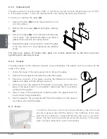
Page 22: ...e backed woven fibreglass The gasket must be centred on the edge of the glass 1 Follow the steps of the previous section to remove the glass 2 Remove the old gasket and clean the glass thoroughly 3 Peel back a section of the paper covering the adhesive and place the gasket on a table with the adhesive side up 4 Stick the end of the gasket to the middle of one edge then press the edge of the glass ...

Page 23: ... forming an inflammable deposit called creosote If creosote builds up in the system it can ignite when a hot fire is burned in the stove A very hot fire can progress to the top of the chimney Severe chimney fires can damage even the best chimneys Smouldering smoky fires can quickly cause a thick layer of creosote to form When the stove is operated properly the exhaust from the chimney is mostly cl...

Page 24: ... fire 6 5 2 Sweeping the Chimney Chimney sweeping can be a difficult and dangerous job People with no chimney sweeping experience will often prefer to hire a professional chimney sweep to inspect and clean the system for the first time After seeing the cleaning process some will choose to do it themselves The chimney should be checked regularly for creosote build up Inspection and cleaning of the ...

Page 25: ...LL CEILING AND ROOF MUST BE MAINTAINED 7 2 Regulations Covering Stove Installation When installed and operated as described in these instructions this wood stove is suitable for use as a freestanding heater in residential installations In Canada the CSA B365 Installation Code for Solid Fuel Burning Appliances and Equipment and the CSA C22 1 Canadian National Electrical Code are to be followed in t...

Page 26: ...the minimum clearance figures given The clearances to combustible walls may be slightly different in Canada and the U S A and may also differ depending on whether single or double wall flue pipe is used The proper clearances should be used depending on the stove location and the type of flue pipe used The clearances of the appliance and the flue pipes must be met individually meaning the appliance...

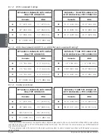
Page 27: ...5 mm E 29 759 mm 29 759 mm F 22 578 mm 22 578 mm F 22 578 mm 22 578 mm 8 1 1 With Heat Shield AC02710 or AC0276214 APPLIANCE CLEARANCES WITH DOUBLE WALL PIPE CONNECTOR DISTANCES13 FROM DOUBLE WALL PIPE CONNECTOR Canada USA Canada USA A 2 64 mm 2 64 mm D 7 184 mm 7 184 mm B 2 64 mm 2 64 mm E 13 340 mm 13 340 mm C 2 64 mm 2 64 mm F 13 337 mm 13 337 mm 13 The pipe distances listed in this table refer...

Page 28: ...13 340 mm C 2 64 mm 2 64 mm F 13 337 mm 13 337 mm L 74 1 880 mm 74 1 880 mm 8 1 4 Inside an Alcove APPLIANCE CLEARANCES WITH DOUBLE WALL PIPE CONNECTOR DISTANCES16 FROM PIPE CONNECTOR WITH DOUBLE WALL PIPE CONNECTOR Canada USA Canada USA A 11 279 mm 11 279 mm D 15 400 mm 15 400 mm B 25 635 mm 25 635 mm E 35 911 mm 35 911 mm K 48 1220 mm 36 910 mm L 74 1 880 mm 74 1 880 mm 15 Note that to reduce th...

Page 29: ...E 15 403 mm 15 403 mm C 3 76 mm 3 76 mm F 13 349 mm 13 349 mm 8 2 Floor Protection This stove is designed to prevent the floor from overheating However it must be placed on a non flammable surface to protect the floor from hot embers that may fall during loading The floor protection must be a continuous non combustible material such as steel with a minimum thickness of 0 015 0 38 mm or ceramic til...

Page 30: ...eat shield between the stove and the flammable material The rules for heat shields are sometimes complicated Read and apply the instructions carefully Some regions may have different regulations Consult the local building code or contact the fire department for restrictions inspection and installation requirements in the area 8 3 1 Shield Construction Rules Adhesives used in shield construction mu...

Page 31: ... the shield 1 25 mm In Canada 21 mm D Clearance along the bottom of the shield minimum 1 25 mm and maximum 3 75 mm E Minimum clearance along the top of the shield at the ceiling 3 75 mm F Mounting hardware must not be located closer than 8 200 mm from the vertical centre line of the appliance G Edge clearance for ceiling shields to side and back walls 3 75 mm H Shield extension beyond each side of...

Page 32: ...le material on non combustible board spaced out at least 1 25 mm by non combustible spacers 50 18 457 mm 33 24 610 mm Ceramic tiles or equivalent non combustible material on non combustible board with a minimum of 24 gauge 0 61 mm sheet metal backing spaced out at least 1 25 mm by non combustible spacers 67 12 305 mm 50 24 610 mm Brick spaced out at least 1 25 mm by non combustible spacers 50 18 4...

Page 33: ...least 5 130 mm Canada only or no more than 7 180 mm is permitted if it allows the proper venting of combustion gases and that such application is verified and authorized by a qualified installer Otherwise the diameter of the flue should be 6 150 mm To be suitable a factory built metal chimney must comply with UL 103 HT U S A or ULC S629 Canada 9 1 1 Factory Built Metal Chimney These are sometimes ...

Page 34: ... must be installed and sealed with silicone adhesive 9 1 3 Masonry Chimney The stove may also be connected to a masonry chimney provided the chimney complies with the construction rules found in the building code enforced locally The chimney must have either a clay liner or a suitably listed stainless steel liner If the masonry chimney has a square or rectangular liner that is larger in cross sect...

Page 35: ...ate fewer creosote deposits and will be unaffected by cold temperatures or harsh winds Outside chimneys will lead to cold back drafting when there is no fire in the stove slow kindling of new fires and smoke roll out when the door is open for loading On the other hand excessive draft will make the fire uncontrollable creating very high temperatures in the unit as well as in the chimney and serious...

Page 36: ...supply of combustion air for a wood stove is from the room in which it is installed Room air is already preheated so it will not chill the fire and its availability is not affected by wind pressures on the house Almost all houses have enough natural leakage to provide the small amount of air needed by the stove The only case in which the wood stove may not have adequate access to combustion air is...

Page 37: ...t tested to a particular standard and certified as compliant Therefore a list of rules found in solid fuel installation codes apply to the installation of single wall pipe 9 5 1 Installation configuration The best installation configuration is the one that rises straight up from the stove to the base of the chimney with no elbows Straight assemblies are less likely to cause problems like smoke rol...

Page 38: ...orize at high temperatures and release dangerous gases Use black painted flue pipes Flue pipes must be at least 24 gauge in thickness Flue pipe joints should overlap at least 1 30 mm Each joint in the assembly must be fastened with at least three screws The installation must allow expansion elbows in assemblies allow for expansion straight assemblies should include an inspection wrap with one end ...

Page 39: ...on of a fresh air intake kit A and an insulated fresh air intake pipe HVAC type must meet ULC S110 or UL 181 class 0 or class 1 B sold separately Refer to air intake kit installation instructions for more details The configutation of this appliance do not allow the air intake to be installed underneath the pedestal It can only be installed at the back A B DETAIL F F ...

Page 40: ... the door opening 3 Lean the upper part of the fire screen against the top door opening making sure to stove the top fire screen brackets behind the primary air deflector 4 Lift the fire screen upwards and push the bottom part towards the stove then let the fire screen rest on the bottom of the door opening Warning Never leave the stove unattended while in use with the fire screen ...

Page 41: ... the stove 1 Remove the backplate by cutting the knockouts with pliers MICROJOINTS 2 Screw the blower A in place using the screws B included in the installation manual Ensure that the blower s power cord is not in contact with any surface of the stove to prevent electrical shock or fire damage Do not run the power cord beneath the stove B A ...

Page 42: ... It allows the fan to operate only when the stove is hot enough See the instructions provided with the thermodisc for more details Screw the thermodisc C with the screws D provided on the back of the stove The electrical cord of the thermodisc should not touch any surface of the stove to avoid electric shock or fire Do not run the power cord under the stove A B ...

Page 43: ...en lift and insert the left end of the tube into the rear left channel 2 Align the notch in the left end of the tube with the key of the left air channel hole Using a Wise grip hold the tube and lock it in place by turning the tube as shown Make sure the notch reaches the end of the key way 3 Put the baffle in place 4 Repeat steps 1 and 2 for the three other tubes 5 To remove the tubes use the abo...

Page 44: ...Page 44 Installation and Operation Manual FW3500 ENGLISH Note that secondary air tubes A can be replaced without removing the baffle board B and that all tubes are identical B A ...

Page 45: ...Page 45 Installation and Operation Manual FW3500 ENGLISH Appendix 6 MOBILE HOME INSTALLATION Screw the base on the floor with the proper hardware ...

Page 46: ... the metal plate C and the refractory brick A 2 Unscrew the two metal rounds using an adjustable wrench 3 Using a hammer remove the third metal rounds 4 Place the ash pan support A in the bottom of the base of the stove 5 Place the refractory brick A the ash plug B and the ash pan C 6 Screw the metal plate A behind the stove A B C A A B C A A B C A B DETAIL F F ...

Page 47: ... 8 EXPLODED DIAGRAM AND PARTS LIST 40 42 14 46 47 48 49 1 45 45 45 45 45 45 45 45 45 45 45 45 45 45 45 45 47 47 47 47 47 46 46 46 50 2 3 4 5 6 7 8 9 8 10 12 13 15 16 17 B DETAIL B 18 19 20 21 22 23 24 25 27 26 29 28 30 31 32 33 34 36 35 11 38 39 41 43 12 37 45 44 51 ...

Page 48: ...NER 2 9 30118 SOCKET SET SCREW HEX 1 4 20 X 3 8 6 10 SE46204 FW3500 INSTRUCTION MANUAL KIT 1 11 AC02055 QUICK CONNECT THERMODISC KIT 1 12 60013 POWER CORD 96 X 18 3 type SJT 50 pcs per carton 2 13 44028 CERAMIC THERMODISC F110 20F 1 14 PL05530 02 THERMODISC BOX COVER 1 15 PL74047 PEDESTAL FRONT COVER 1 16 30060 THREAD CUTTING SCREW 1 4 20 X 1 2 F HEX STEEL SLOT WASHER C102 ZINC 4 17 PL74018 ASH SH...

Page 49: ...ED CONTROL UP TO 100 CFM 1 39 PL09909 02 BLOWER HOUSING 1 40 44080 RHEOSTAT WITHOUT NUT MODEL KBMS 13BV 1 41 44087 RHEOSTAT NUT 1 42 44085 RHEOSTAT KNOB 1 43 44073 CROSSFLOW BLOWER 115V 60Hz 39W 100 CFM 1 44 PL74051 4 1 2 X 7 1 2 X 1 1 4 REFRACTORY BRICK 1 45 29010 4 1 2 X 9 X 1 1 4 REFRACTORY BRICK 17 46 29015 4 X 9 X 1 1 4 REFRACTORY BRICK 4 47 PL36759 2 X 9 X 1 1 4 REFRACTORY BRICK 8 48 PL70864...

Page 50: ...cide to repair or replace any part or unit after inspection and investigation of the defect The manufacturer may at its discretion fully discharge all obligations with respect to this warranty by refunding the wholesale price of any warranted but defective parts The manufacturer shall in no event be responsible for any uncommon indirect consequential damages of any nature which are in excess of th...

Page 51: ...Page 51 Installation and Operation Manual FW3500 ENGLISH NOTES ...

Page 52: ...rnational com This document is available for free download on the manufacturer s website It is a copyrighted document Resale is strictly prohibited The manufacturer may update this document from time to time and cannot be responsible for problems injuries or damages arising out of the use of information contained in any document obtained from unauthorized sources ...

Reviews: