9
3.2 Preliminary planning for mounting the
installation
Some preliminary planning is necessary before starting to
mounting the system.
Selecting the suitable constructions and rafter con-
figuration
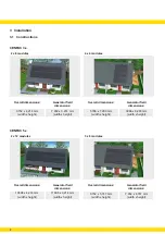
Calculate the available connected roof surface and rafter
distance for the installation. Select the suitable CENPAC
construction based on the roof dimensions and the nec-
essary
overall dimensions
of the CENPAC constructions
(see chapter 3.1). A choice must finally be made from the
rafter configuration plans (see installation instructions)
that corresponds to the distance of your rafters. Proceed
in accordance with chapter 3.3 if there is a difference in
rafter distances.
Positioning the PV installation
Position your CENPAC bearing in mind the
Generator field
dimensions
as close as possible to the centre of the roof.
Bear in mind that a
margin
of at least 500 mm must be
observed at all times. The actual mounting can now begin
(chapter 4).
If the distance relating to your rafters differs from that in
the drawings and you cannot carry out your
rafter con-
figuration
yourself in accordance with chapter 3.3, please
contact your local Centrosolar office.
3.3 Rules relating to individual rafter
configuration
P
P
Rafter distances of 600 – 800 mm are permitted
P
P
Max. range that can be straddled with the module
supports: 1,500 mm
P
P
Permissible cantilever: 50 – 400 mm
P
P
Carry out the rafter configuration on the sides of the
generator field on the two outer rafters
P
P
Twice the number of roof hooks on the 2-C groove
profiles in the border of the generator field (to the
ridge, the eaves and the verges)
P
P
Module support profiles must be fixed on at least two
2-C groove profiles
Terminology
Overall dimensions
The overall dimensions state the free roof space that must
be available for the installation of the complete CENPAC
system in order to enable the CENPAC to be installed on
your roof safely. The overall dimensions also included the
necessary margins and an additional rafter adjustment
area as well as the generator field dimensions.
Generator field dimensions
The generator field dimensions are clear from the genera
-
tor surface of all PV modules of the complete CENPAC
system.
Margins
The margins stated here are safety-relevant distances of
500 mm to which your PV installation must at least adhere
to the eaves, the ridge and the verge of the roof.
Cantilever
The cantilever is the overhang of the module support pro-
files over the external 2-C groove profile in the generator
field. The permissible cantilever may be between 50 and
400 mm. During the preliminary mounting planning, the
cantilever is defined by the overhang of the module sup
-
port profiles over the centre of the outer rafters.
Rafter configuration plans
These are CAD plans for the rafter configuration on the
roof. These plans for the rafter distances of 600, 650, 700,
750 and 800 mm for the individual constructions of the
complete CENPAC system are enclosed. They explain
the optimal configuration of the rafters by way of the en
-
closed roof hooks, the positioning of the mounting profiles
as well as the cantilever to be applied.
Summary of Contents for CENPAC 3 Series
Page 1: ...www centrosolar com www centrosolar co uk CENPAC Mounting instructions CENPAC 3 x CENPAC 5 x...
Page 2: ......
Page 4: ...4...
Page 22: ...Notes 22...
Page 23: ......


