background image

Page 6

SKU 92918

For technical questions, please call 1-800-444-3353.

SAFETY

(59)

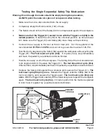
AIR INLET (61)

EXHAUST

COVER (2)

TRIGGER

LOCK (28)

Testing the Single Sequential Safety Trip Mechanism

Warning: Even though the nailer should be empty during this procedure,

ALWAYS point the nailer at a piece of scrap wood when testing.

1.

Make sure the tool is disconnected from the air supply.

2.

Completely empty the Nail Canister (100) of nails.

3.

The Nailer should not fire if the Safety (59) is not depressed against the workpiece.

4.

Make sure that the Trigger (51) cannot move with the Trigger Lock (28) in the
locked position.

  Rotate the Lock (28) to the unlocked position, as shown below

left.  Make sure the Trigger (51) and Safety (59) move freely, without sticking.

5.

Connect the air supply to the tool at the Air Inlet (61).  Set the regulator at the
recommended 

70 PSI

 to 

125 PSI

, and set not to go over the maximum 125 PSI.

6.

Test the tool by depressing the Safety (59) against the workpiece without pulling the
Trigger (51).  

The Tool must not cycle (fire).   

If it cycles (fires), stop immediately

and have it repaired by a qualified service technician.

7.

Hold the tool away or off of the workpiece.  The Safety (59) of the tool should return
to its original position.  Squeeze the Trigger (51).  

The tool should not cycle (fire).

If the tool fires, stop immediately and have it repaired by a qualified service technician.

8.

Depress the Safety (59) against the workpiece and squeeze the Trigger (51).  

The

tool must cycle (fire) only once.  

Release the Trigger, slide the Safety (59) of the

tool over slightly, and squeeze the Trigger again.

  The tool must cycle (fire) only

once.  

With the Trigger held, carefully lift the nailer and press it against the workpiece

again.  

The tool must not cycle (fire).

  If it fails to perform in the manner explained

in bold, have it repaired by a qualified service technician.

TRIGGER

(51)

Rev 11/06

Summary of Contents for 92918

Page 1: ...005 by Harbor Freight Tools All rights reserved No portion of this manual or any artwork contained herein may be reproduced in any shape or form without the express written consent of Harbor Freight Tools For technical questions and replacement parts please call 1 800 444 3353 TO PREVENT SERIOUS INJURY READ AND UNDERSTAND ALL WARNINGS AND INSTRUCTIONS BEFORE USE ...

Page 2: ...wear m e t I n o i t p i r c s e D y t i c a p a C h t g n e L r e n e t s a F d e t a l l o C c i t s a l P g n o L 2 1 2 o t 4 3 1 d e t a l l o C e r i W g n o L 2 1 2 o t 4 1 1 e g u a G r e n e t s a F r e t e m a i D 9 9 0 2 8 0 s k n a h S l i a N e g u a G 2 1 4 1 y t i c a p a C e n i z a g a M s l i a N 0 5 3 0 5 2 I S P g n i t a r e p O I S P 5 2 1 o t 0 7 n o i t p m u s n o C r i A I...

Page 3: ... air even after disconnecting hose Disconnect the Nailer when not in use 11 Remove adjusting keys and wrenches Check that keys and adjusting wrenches are removed from the tool or machine work surface before attaching to an air source 12 Avoid unintentional starting Be sure the trigger is in the Off position when not in use and before plugging in Do not carry any tool with your finger on the trigge...

Page 4: ...ur Do not load nails when the air hose is connected to the tool Always assume the tool contains fasteners 21 Disconnect air supply before loading the Nailer Before reloading or making any adjustments to the Nailer make sure the compressed air is disconnected 22 Fire fasteners into an appropriate work surface only Do not attempt to fire fasteners into surfaces too hard to penetrate Do not drive fas...

Page 5: ...ion manual cannot cover all possible conditions and situations that may occur It must be understood by the operator that common sense and caution are factors which cannot be built into this product but must be supplied by the operator Unpacking When unpacking check to make sure all parts shown in the Parts List on page 13 are included If any parts are missing or broken please call Harbor Freight T...

Page 6: ...d 70 PSI to 125 PSI and set not to go over the maximum 125 PSI 6 Test the tool by depressing the Safety 59 against the workpiece without pulling the Trigger 51 The Tool must not cycle fire If it cycles fires stop immediately and have it repaired by a qualified service technician 7 Hold the tool away or off of the workpiece The Safety 59 of the tool should return to its original position Squeeze th...

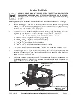
Page 7: ...rom 11 4 to 21 2 To help prevent jamming nails under 13 4 must be wire collated A For 11 4 to 11 2 Long Nails Use first top setting B For 15 8 to 13 4 Long Nails Use second setting C For 2 to 21 4 Long Nails Use third setting D For 23 8 to 21 2 Long Nails Use fourth bottom setting 3 Place a coil of nails around the Canister Platform 96 in the Nail Canister 100 4 Uncoil enough nails to reach the Fe...

Page 8: ...ke some practice and experience to get the desired results If more depth adjustment is needed the air supply pressure can be adjusted but ONLY within the recommended 70 125 PSI 4 The direction of the air exhaust can be changed by loosening the Exhaust Screw 1 in the center of the Exhaust Cover 2 rotating the Exhaust Cover to the desired direction and retightening the Exhaust Screw 1 5 Do not press...

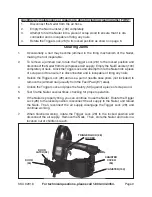
Page 9: ...fire the Nailer several times checking for proper operation 6 If the Nailer is properly firing you can continue to use the Nailer Rotate the Trigger Lock 28 to the locked position disconnect the air supply to the Nailer and reload the Nails Then reconnect the air supply disengage the Trigger Lock 28 and continue working 7 When finished working rotate the Trigger Lock 28 to the locked position and ...

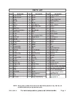
Page 10: ...MANUFACTURER AND OR DISTRIBUTOR HAS PROVIDED THE PARTS DIAGRAM INTHIS MANUAL AS A REFERENCETOOLONLY NEITHERTHEMANUFACTURERNORDISTRIBUTORMAKESANYREPRESENTATION ORWARRANTY OF ANY KINDTOTHE BUYERTHAT HE OR SHE IS QUALIFIEDTO MAKE ANY REPAIRSTOTHE PRODUCT OR THAT HE OR SHE IS QUALIFIED TO REPLACE ANY PARTS OF THE PRODUCT IN FACT THE MANUFACTURER AND OR DISTRIBUTOR EXPRESSLY STATES THAT ALL REPAIRS AND...

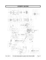
Page 11: ... e l S 1 9 n i P 8 1 g n i R r e d n i l y C 4 5 g n i r p S 2 9 r e v o C 9 1 g n i R r e d n i l y C 5 5 b a T 3 9 t u N t r e s n I n o l y N 0 2 r e d n i l y C 6 5 r e t s u j d A h t p e D 4 9 r e v o C r e t s i n a C 1 2 g n i r O 7 5 g n i r O 5 9 p a C m r o f t a l P 2 2 g n i R r e d n i l y C 8 5 g n i R g n i n i a t e R 6 9 m r o f t a l P 3 2 g n i r O 9 5 y t e f a S 7 9 r e h s a...

Page 12: ...Page 12 SKU 92918 For technical questions please call 1 800 444 3353 ASSEMBLY DIAGRAM ...

Reviews: