Central Machinery 99553 Set Up And Operating Instructions Manual Download Page 18

SKU 99553 

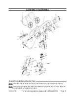
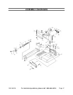
For technical questions, please call 1-800-444-3353. 

Page 18

limited 1 Year / 90 daY warrantY

Harbor Freight Tools Co. makes every effort to assure that its products meet high 

quality and durability standards, and warrants to the original purchaser that for a period 

of ninety days from date of purchase that the engine/motor, the belts (if so equipped), 

and the blades (if so equipped) are free of defects in materials and workmanship. Har-

bor Freight Tools also warrants to the original purchaser, for a period of one year from 

date of purchase, that all other parts and components of the product are free from 

defects in materials and workmanship (90 days if used by a professional contractor or 

if used as rental equipment).  This warranty does not apply to damage due directly or 

indirectly, to misuse, abuse, negligence or accidents, repairs or alterations outside our 

facilities, normal wear and tear, or to lack of maintenance. We shall in no event be liable 

for death, injuries to persons or property, or for incidental, contingent, special or con-

sequential damages arising from the use of our product. Some states do not allow the 

exclusion or limitation of incidental or consequential damages, so the above limitation 

of exclusion may not apply to you.

  THIS WARRANTy IS ExPRESSLy IN LIEU OF ALL 

OTHER WARRANTIES, ExPRESS OR IMPLIED, INCLUDINg THE WARRANTIES OF 

MERCHANTABILITy AND FITNESS.

To take advantage of this warranty, the product or part must be returned to us with 

transportation charges prepaid. Proof of purchase date and an explanation of the com-

plaint must accompany the merchandise. If our inspection verifies the defect, we will ei

-

ther repair or replace the product at our election or we may elect to refund the purchase 

price if we cannot readily and quickly provide you with a replacement. We will return re-

paired products at our expense, but if we determine there is no defect, or that the defect 

resulted from causes not within the scope of our warranty, then you must bear the cost 

of returning the product.

This warranty gives you specific legal rights and you may also have other rights 

which vary from state to state.

3491 Mission Oaks Blvd.  •  PO Box 6009  •  Camarillo, CA 93011  •  (800) 444-3353

Summary of Contents for 99553

Page 1: ...ht 2008 by Harbor Freight Tools All rights reserved No portion of this manual or any artwork contained herein may be reproduced in any shape or form without the express written consent of Harbor Freight Tools Diagrams within this manual may not be drawn proportionally Due to continuing improvements actual product may differ slightly from the product described herein Tools required for assembly and...

Page 2: ... Prong Plugs 8 Extension Cords 8 Symbology 9 Specifications 9 Unpacking 9 Instructions for putting into use 9 Operating Instructions 10 Tool Set Up 10 Depth Gauge 10 Adjusting the Blade Guide 10 Adjusting Cutting Angle 11 Handwheel 11 Work Piece and Work Area Set Up 11 General Operating Instructions 11 Maintenance And Servicing 12 Cleaning Maintenance and Lubrication 12 Replacing the Blade 13 Part...

Page 3: ...afety alert symbol indicates a hazardous situation which if not avoided could result in minor or moderate injury NOTICE is used to address practices not related to personal injury CAUTION without the safety alert symbol is used to address practices not related to personal injury General Power Tool Safety Warnings WARNING Read all safety warnings and instructions Failure to follow the warnings and ...

Page 4: ...power tools may result in serious personal injury Use personal protective equip b ment Always wear eye protection Safety equipment such as dust mask non skid safety shoes hard hat or hearing protection used for appropri ate conditions will reduce personal injuries Prevent unintentional starting c Ensure the switch is in the off po sition before connecting to power source and or battery pack pick i...

Page 5: ...poorly maintained power tools Keep cutting tools sharp and f clean Properly maintained cutting tools with sharp cutting edges are less likely to bind and are easier to control Use the power tool accessories g and tool bits etc in accordance with these instructions taking into account the working conditions and the work to be performed Use of the power tool for operations differ ent from those inte...

Page 6: ...9 5 et seq The warnings precautions and in 8 structions discussed in this instruction manual cannot cover all possible con ditions and situations that may occur It must be understood by the operator that common sense and caution are factors which cannot be built into this product but must be supplied by the operator Vibration Safety This tool vibrates during use Re peated or long term exposure to ...

Page 7: ... outlet installed by a qualified electrician Grounded Tools Tools with Three Prong Plugs Tools marked with Grounding Re 1 quired have a three wire cord and three prong grounding plug The plug must be connected to a properly grounded outlet If the tool should electrically malfunction or break down grounding provides a low resistance path to carry electricity away from the user reducing the risk of ...

Page 8: ... with inadequately sized wire causes a serious drop in voltage resulting in loss of power and pos sible tool damage See Table A The smaller the gauge number of the 3 wire the greater the capacity of the cord For example a 14 gauge cord can carry a higher current than a 16 gauge cord See Table A When using more than one exten 4 sion cord to make up the total length make sure each cord contains at l...

Page 9: ...Cutting Capacity Round Stock Rectangular Stock Round Stock Rectangular Stock 5 5 16 90 5 7 8 x 5 1 2 90 3 1 2 45 3 15 16 x 3 1 2 45 Table Pivot 0 60 Left tilt only Blade Length 67 1 2 Blade Tooth Per Inch 10 TPI Blade Feet Per Minute 213 FPM Unpacking When unpacking check to make sure that the item is intact and undamaged If any parts are missing or broken please call Harbor Freight Tools at the n...

Page 10: ... Bracket 84 Figure 1 1 The Band Saw has a Depth Gauge for cutting several pieces of the same length see Figure 1 Thread the Stop Bracket into the 2 Base 85 Insert Stop Rod 81 Loosen the Set Bolt 82 and move 3 Stop Rod 81 to stop workpiece at desired depth Tighten Set Bolt 82 Adjusting the Blade Guide Screw Bolt 25 Figure 2 1 The Blade Guide is adjustable to pro tect the part of the blade not in us...

Page 11: ...low free movement while working Secure loose work pieces using a 3 vise or clamps not included to pre vent movement while working There must not be hazardous ob 4 jects such as utility lines or foreign objects nearby that will present a hazard while working General Operating Instructions Hex Bolts Handle 28 Figure 4 1 Loosen the Hex Nuts see Figure 4 to Adjust the Handle 28 to the de sired positio...

Page 12: ...rious injury from tool failure Do not use damaged equipment If abnormal noise or vibration occurs have the problem corrected before further use Cleaning Maintenance and Lubrication BEFORE EACH USE 1 inspect the general condition of the tool Check for loose screws misalignment or binding of moving parts cracked or broken parts damaged electrical wir ing and any other condition that may affect its s...

Page 13: ...o make any repairs to the product or that he or she is qualified to replace any parts of the product In fact the manufacturer and or distributor expressly states that all repairs and parts replacements should be undertaken by certified and licensed technicians and not by the buyer The buyer assumes all risk and liability arising out of his or her repairs to the original product or replacement part...

Page 14: ...r 1 50 Miter Plate 1 51 Nut 1 52 Washer 1 53 Screw 1 54 Nut 1 55 Plate 1 56 Locking Handle 1 57 Washer 1 58 Screw 1 59 Scale 1 60 Screw 1 60 1 Washer 1 61 Bushing 1 62 Washer 1 63 Screw 1 64 Screw 1 65 Nut 1 66 Screw 1 67 Vise Plate 1 68 Screw 1 69 Washer 1 70 Vise Screw 1 71 Washer 1 72 Pin 1 73 Busing 1 74 Screw 1 75 Handle Wheel 1 Parts List Part Description Qty 76 Washer 1 77 Screw 1 78 Vise 1...

Page 15: ... 1 M4 C Ring 1 M5 Gear 1 M6 Key 2 M7 Gear Shaft 2 M8 Gear Box 1 M9 Bearing 2 M10 Oil Seal 2 M11 Gear 2 M12 UP Cover 2 M13 Screw 4 x 45 mm 2 M14 Nut 22 M15 Fan 2 M16 Screw 2 M17 Electrical Board 1 M18 Oil Seal 2 M19 Motor 2 M20 Switch 2 M21 Down Cover 2 M22 Plug 2 M23 Handle Wire 2 M24 Main Shaft 1 M25 Key 1 M26 Bearing 1 M27 Middle Plastic Cover 1 ...

Page 16: ...ge 16 ASSEMBLY DIAGRAM A Record Product s Serial Number Here Note If product has no serial number record month and year of purchase instead Note Some parts are listed and shown for illustration purposes only and are not avail able individually as replacement parts ...

Page 17: ...SKU 99553 For technical questions please call 1 800 444 3353 Page 17 ASSEMBLY DIAGRAM B ...

Page 18: ... or for incidental contingent special or con sequential damages arising from the use of our product Some states do not allow the exclusion or limitation of incidental or consequential damages so the above limitation of exclusion may not apply to you This warranty is expressly in lieu of all other warranties express or implied including the warranties of merchantability and fitness To take advantag...

Reviews: