

SKU 99553
For technical questions, please call 1-800-444-3353.
Page 13
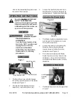
Place new Saw Blade (4) in between
5.
each of the guide bearings, with the
teeth facing downward-see Figure 6.
Slip the Saw Blade around the Motor
6.
Flywheel (41).
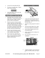
Figure 7
Saw Blade (40)
Tensioning
Knob
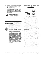
7. Keeping blade taut against the Mo-
tor Flywheel, place the other end of
the blade on the Return Flywheel
(39)-see Figure 7.
Using Tensioning Knob, adjust blade
8.
tension so that no slippage occurs.
Do not overtighten.
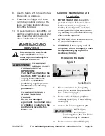
Replace Body Cover (43) with
9.
Screws (42).
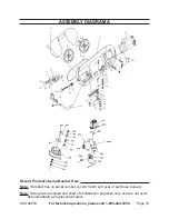
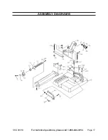
pleaSe read tHe FOllOwing
careFullY
THE MANUFACTURER AND/OR DISTRIBUTOR
HAS PROvIDED THE PARTS LIST AND
ASSEMBLy DIAgRAM IN THIS MANUAL AS
A REFERENCE TOOL ONLy. NEITHER THE
MANUFACTURER OR DISTRIBUTOR MAKES
ANY REPRESENTATION OR WARRANTY OF
ANY KIND TO THE BUYER THAT HE OR SHE
IS qUALIFIED TO MAKE ANy REPAIRS TO THE
PRODUCT, OR THAT HE OR SHE IS qUALIFIED
TO REPLACE ANy PARTS OF THE PRODUCT.
IN FACT, THE MANUFACTURER AND/OR
DISTRIBUTOR ExPRESSLy STATES THAT
ALL REPAIRS AND PARTS REPLACEMENTS
SHOULD BE UNDERTAKEN By CERTIFIED
AND LICENSED TECHNICIANS, AND NOT By
THE BUyER. THE BUyER ASSUMES ALL RISK
AND LIABILITy ARISINg OUT OF HIS OR HER
REPAIRS TO THE ORIgINAL PRODUCT OR
REPLACEMENT PARTS THERETO, OR ARISINg
OUT OF HIS OR HER INSTALLATION OF
REPLACEMENT PARTS THERETO.
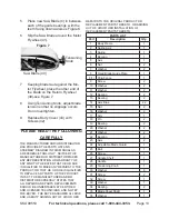
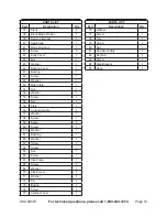
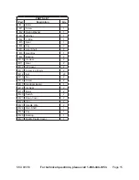
partS liSt
part
description
Qty.
1
Body Frame
1
2
Spring Axis
1
3
Spring
1
4
Bearing
1
5
Axis
1
6
Nut
2
7
Washer
2
8
Fixed Blade Guide Plate
1
8 (1) Chip Fence
1
9
Screw
2
10
Washer
2
11
Washer
2
12
Bearing
2
13
Bearing
2
14
Axis Bias
22
15
Nut
2
16
Washer
2
17
Arm
1
18
Pin
2
19
Bearing
2
20
Washer
2
21
Washer
2
22
Bearing
2
23
Axis
2
24
Adjustable Blade Guard
1
25
Bolt
1
26
Screw
1
27
Handle Shelf
1
28
Handle
1
29
Tensioning Knob
1
30
Washer
8
31
Screw
2
32
Screw
1
33
Washer
1
34
Bearing
2
35
Blade Sheet Shaft
1
36
Washer
1