


10
25
Before servicing or maintenance, stop the motor and disconnect the plug
from the electric source
After fi rst 10 oerating hours, proceed with sump oil change, as follows:
(Ref. to Fig. 28)
– Remove the cap with the magnetic insert (21).
– Remove oil fi ller cap (07).
– Make sure that all the oil comes out by slightly tilting the drill.
– Clean up the cap (21) (see § 13.1.2).
– Reassemble the cap (21).
– Fill the sump with oil to the level indicator (see § 13.1.1) using the oil supplied with the
drilling machine; it will be necessary to use about 4.7 fl oz oil.
– Replace the fi ller cap (07).
13.1) ORDINARY MAINTENANCE OF THE MACHINE (Ref. to Figs. 24 and 28)
Every 20 hours of operation
13.1.1) Topping up oil
With the drill switched off and placed on a fl at surface, check the oil level in the crankcase
by looking through the appropriate transparent inspection cover (13).
The level must be approximately half way up the cover; if the level is low top up the oil
by unscrewing the cover (07) at the top of the crankcase and adding the quantity of oil
required.
Only use the oil grade recommended in § 1.
Never use regenerated or used oil.
The oil must be clean.
13.1.2) Removal of metallic residue
from the crankcase
When the drill is positioned as shown
in Fig. 24 unscrew the appropriate cap,
with magnetic insert (21) on which any
metallic residue will have collected.
Carefully clean the magnetic insert
with a clean rag and screw it back in
the appropriate housing.
▲
!
FIG. 24 – REMOVAL OF
METALLIC RESIDUE
21
13. MAINTENANCE
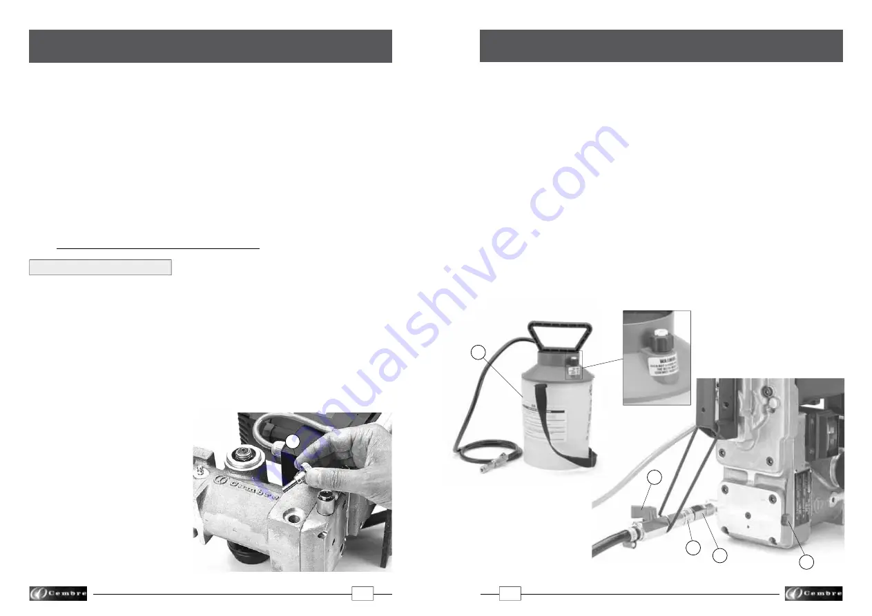
The type SR5000 coolant unit consists of a tank complete with tube and maximum pressure
valve (01), fi tted with a pump device for pressurisation, which must be connected to the
attachment (35) on the drill by means of its quick-coupling (03).
The delivery and shut-off of the lubrocoolant are controlled automatically, when drilling
with a broach cutter, from the position of the guide bit; when drilling with a spiral bit,
delivery and shut-off of the fl uid must be effected manually by operating the tap (02).
The use of the lubrocoolant supplied by
Cembre
, in the recommended concentrations,
guarantees optimum use of the drilling tools.
Consumption of the lubrocoolant depends both on the variable degree of opening
of the tap (02) and the inner pressure of the tank: it is therefore advisable to open
the tap a little when the tank is at maximum pressure, while it must be fully opened
when the pressure in the tank is low.
When using the coolant system, pay careful attention to the instructions on the tank label.
Warning:
●
When the tank is not under pressure, check that the bush on the maximum pres-
sure valve is screwed right down.
●
To fi ll tank with lubrocoolant, turn handle anticlockwise approximately 2 turns to
release handle locking mechanism. Remove handle/piston assembly from tank.
02
03
35
17
01
Detail of the
max pressure valve
FIG. 3 – COOLANT UNIT
01 – Tank complete with hose
and max. pressure valve
02 – Tap
03 – Quick-coupling
17 – Vent valve
35 – Attachment valve
4. Type SR5000 COOLANT UNIT (Ref. to Fig. 3)