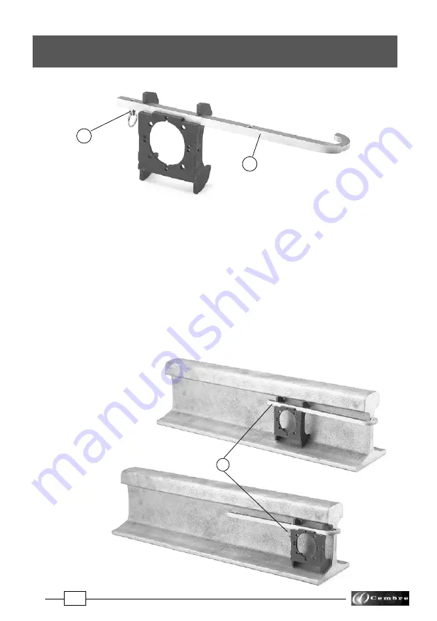
Cembre LD-1P-ECO Operation And Maintenance Manual Download Page 23

23

02

11.1.1) 

Fit the 

MPAF...

 positioning template corresponding to the rail to be drilled (see § 7.3).

11.1.2)

  Insert the 

SPA...

 positioning plate (03) relating to the rail to be drilled in the appropriate 


housing (see Fig. 21).

11.1.3)

  Insert the locking pin (02) in one of the two holes of the connection plate.

11.1.4)

  With the spindle fully withdrawn position the drill close to the rail head without clamp-


ing  it.

11.1.5)

  Slide the drill so that:


–  the curved end of the SPA... plate is flush against the rail head.


–  the MPAF... positioning template is flush against the locking bolt (02).

11.1.6)

  Clamp the drill in this position by tightening the handwheel fully, and commence drilling 


(see § 8.1).

11.1.7)

  To drill the second hole in the rail, repeat operations 11.1.5 - 6 with the locking pin (02) 


inserted in the second hole of the 

SPA...

 plate.

11.1)  Instruction for drilling close to rail heads 

FIG. 21

02

03

For clarity the drilling 
machine is not shown.

FIG. 22 – POSITIONING

11. SPA... POSITIONING PLATE

Summary of Contents for LD-1P-ECO

Page 1: ...LISH OPERATION AND MAINTENANCE MANUAL 15 M 067 E RAIL DRILL TYPE LD 1P ECO Certi ed Environmental Management System Certi ed Occupational Health Safety Management System Certi ed Quality Management Sy...

Page 2: ...INSTRUCTIONS this manual contains important safety and operating instructions for the drill STOP THE ENGINE when servicing the drill before removing the broach cutters spiral bits positioning templat...

Page 3: ...uivalent A at the work place LpA is equal to 99 5 dB A The maximum value of the weighted acoustic displacement pressure C at the work place LpCPeak is equal to 116 3 dB C The acoustic power level emit...

Page 4: ...h the SR5000 cooling unit 2 4 Grub screw M8x10 4 pcs for clamping cutters or bits on the spindle shaft 2 5 Socket head cap screws M6x16 4 pcs for securing positioning templates to the front plate 2 6...

Page 5: ...g the drill complete with the DBG F2 device and accessories Also available VAL P24 CS plastic carrying case with folding handle and wheels 3 2 1 VAL LD L metal case for storing the drill complete with...

Page 6: ...ositioningtemplatesuitablebothforrepair ingexistingholesonvariousfittings andfordrillingdisusedrails 3 8 MRF clamp to be applied as a reference to the head of rails for use in conjunction with the SPA...

Page 7: ...CY130 CY135 CY160 CY170 CY175 CY180 CY190 CY200 CY210 CY220 CY230 CY240 CY250 CY260 CY270 CY275 CY280 CY290 CY300 CY310 CY320 CY330 mm 13 13 5 14 16 17 17 5 18 19 20 21 22 23 24 25 26 27 27 5 28 29 30...

Page 8: ...ive temperature conditions 3l Special spiral bits in the PE range allow automatic cooling by means of the SR5000 unit supplied with the drilling machine All spiral bits in the PE range allow drilling...

Page 9: ...by operating the tap 02 The use of the lubrocoolant supplied by Cembre in the recommended concentrations guarantees optimum use of the drilling tools Consumption of the lubrocoolant depends both on t...

Page 10: ...e interchanged proceed as follows With a 17 mm hexagonal key unscrew the vent valve from its seat Using the 4 mm Allen key provided with the drill remove the attachment cooling valve from its seat and...

Page 11: ...ressed theleverisreleased fromitshubandcanrepeattheprevioustravelwithout the spindle moving 6c Withthehubreleased movingthelevertowards theoperatorcausesacorrespondingadvanceof the spindle FIG 7 6a Mo...

Page 12: ...dogs on the cutter spigot line up with the grub screws 18 6 1 4 Clamp the cutter by fully tightening the grub screws using the 4 mm allen key 6 1 5 Check that the guide bit slides freely by applying...

Page 13: ...priate grub screw Then the DPE spacer may be inserted Note Adapters type APED do not require use of DPE spacer 6 2 3 Insert the bit spacer unit in the spindle shaft so that the two engaging dogs on th...

Page 14: ...ping it to the rail web and the track fittings Ref to Fig 12 The DBG F2 device consists of Clamping unit Type TDB 1 termination Type TDB 3 termination Type TDB 6 termination Socket head cap screws M 8...

Page 15: ...ositioning pawl pointing downwards holding plate 7 1 Assemble of the terminations of the DBG F2 device with moving arm for clamping the drill to the rail web and track fittings The terminations TDB 1...

Page 16: ...itioning templates are secured to the front plate 04 of the drill by means of the two socket head cap screws M 6x16 supplied FIG 14 ASSEMBLY OF THE DBG F2 CLAMP screws M6x16 MPAF MPAU DBG F2 Clamp Dri...

Page 17: ...ally position the cutter or drill bit in line with the designated axis if precise positioning is necessary to the longitudinal rail axis use the reference pin 01 7 4 4 For rapid drill release simply b...

Page 18: ...Move engine ON OFF switch to the ON position Fig a 9 2 Repeatedly operate the fuel pump until fuel flows through the overflow pipe Fig b a WARNING To avoid an electric shock do not touch spark plug pl...

Page 19: ...e the carburettor 9 5 Just after starting accelerate the engine gradually before starting any activity then set the accelerator lever in 1 position Fig e till the choke lever automatically returns the...

Page 20: ...e drill being clamped to the rail 7 3 as follows 10 1 1 Connect the female quick coupling of the SR5000 cooling system to the male attachment 35 on the drill 10 1 2 Open the tap 02 fitted on the tank...

Page 21: ...er may be damaged 10 1 6 The guide bit will enable the lubrocoolant to be discharged throughout the drilling process 10 1 7 When the drilling has been completed fully retract the spindle stop the engi...

Page 22: ...tted with special spiral bit Follow the sequence described in 10 1 taking care to position the drill on the rail by keeping thespindlefullywithdrawn Bearinmindthatthecoolingcircuit insteadofbeingautom...

Page 23: ...ead without clamp ing it 11 1 5 Slide the drill so that the curved end of the SPA plate is flush against the rail head the MPAF positioning template is flush against the locking bolt 02 11 1 6 Clampth...

Page 24: ...acing upwards 11 2 4 Insert the locking pin 02 in one of the two holes of the connection plate 11 2 5 With the spindle fully withdrawn position the drill on the rail close to the MRF clamp without loc...

Page 25: ...25 Origin of the distances 02 Origin of the distances For clarity the drilling machine is not shown 02 FIG 24 POSITIONING...

Page 26: ...e drill and the SR5000 cooling unit in a sealed place free from dust moisture and the risk of accidental impact For better protection Cembre recommends the use of the VAL P24 plastic carrying case or...

Page 27: ...tor see 13 1 1 using the oil supplied with the drilling machine it will be necessary to use about 100 ml Replace the oil filler cap 08 Ensure that disposal of used oil is in accordance with cur rent l...

Page 28: ...1 4 Lubrication Ref to Figs 31 and 32 Lubricate the spindle support housing by means of the appropriate lubricator 21 the screw 07 of the DBG F2 clamping device 13 1 5 Coolant filter cleaning Ref to F...

Page 29: ...ausing problems with starting or running the engine At the same time make sure that the base of the breather assembly is fitted firmly into the groove inside the tank cap as shown Every 20 hours of op...

Page 30: ...ust if necessary the electrode gap 0 6 mm 0 7 mm Install and tighten the spark plug to 14 Nm then connect the spark plug lead In case of plug replacement use type NGK BPMR7A or equivalent BOSCH WSR5F...

Page 31: ...F2 clamping device be removed make sure by reassembling it the two blocking screws are firmly fastened 14 WARNINGS 13 2 6 Checking of screws Check and re tighten all screws where necessary 13 3 SPECI...

Page 32: ...are not Cembre original spares When ordering spare parts always give the following information spare part code spare part description drilling machine model drilling machine serial number FIG 31 DRILL...

Page 33: ...Handle Complete handgrip Cap Accelerator lever Carriage handle Complete spindle lever O ring Lever release pawl Completecoolingconnection Body 1 1 1 1 1 1 1 1 1 1 1 1 Item Qty Description Code N 60012...

Page 34: ...rew Spacer Bush Cup spring 2 5x16 split pin Blocking support Reference pin Code N Item Description Qty 37 36 35 34 33 32 31 29 28 27 26 25 24 23 22 21 20 19 18 17 16 15 14 13 11 10 09 08 07 06 05 04 0...

Page 35: ...time facilitating the removal of swarf Contact time of the cutting edges of the cutter with the material to be drilled bear in mind that the faster the hole is made the greater the efficiency Observan...

Page 36: ...les cembre com www cembre it Cembre S a r l 22 Avenue Ferdinand de Lesseps 91420 Morangis France T l 01 60 49 11 90 Fax 01 60 49 29 10 CS 92014 91423 Morangis C dex E mail info cembre fr www cembre fr...

Reviews: