background image


- 13 -

Service Guide 


CAUTION: 


ALWAYS USE THE SUPERHEAT AND SUBCOOLING, PRESSURE 
READINGS TO CHARGE REFRIGERANT PROPERLY, THE LISTED 
CHARGES ARE FOR REFERENCE ONLY. 


CHARGE 15% MORE REFRIGERANT IN THE SUMMER IF THE UNIT IS 
EQUIPPED A LOW AMBIENT CONDITION KIT 

NOTES: 


THE VALVE CONNECTION SIZES OF CONDENSING UNIT AND THE LINE 
CONNECTION SIZES OF EVAPORATOR UNIT ARE NOT NECESSARY 
THE SAME AS THE ABOVE SPECIFIED LINE SIZES. 


IF THE CONDENSING UNIT IS INSTALLED ABOVE THE EVAPORATOR 
UNIT, USE THE SUCTION LINE ONE LISTED SIZE SMALLER. 


EXPANSION AND SOLENOID VALVES ARE INSTALLED ON LIQUID LINE. 


1. Refrigeration Piping, Evacuating, Charging and Starting 
  

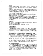
  The installation order starts from condensing unit (including the receiver, 

discharge valve), liquid line filter-drier, moisture-liquid indicator/sight glass, 
liquid line, to evaporator unit (including liquid line connection, solenoid 
valve, expansion valve, and suction line connection), returning to insulated 
suction line, suction valve and then condensing unit.  

  Use inverted siphons to prevent liquid from flooding back to the 

compressor and aid oil returning to the compressor. 

  Charge the system after pipe brazing, leak testing and evacuating. Liquid 

must always be charged into the hide side. 

  It may use fan speed control to adjust the air flow to achieve the specified 

CFM. Turn control knob clockwise to the lowest speed position, locate and 
adjust the minimum speed setting (on the side or front) with screw driver. 
Rotate the setting clockwise to decrease minimum speed or counter-
clockwise to increase minimum speed). The minimum speed should be 
adjusted until it supplies the required CFM. The fan will run from this 
preset minimum speed to full speed with the control knob at lowest and 
highest speed position. 

  The subcooling at the condensing unit shall be around 10

° 

F. The charge 

may be complete when there are no more bubbles forming in the sight 
glass. 

  Head pressure: 125-150 psig at 70 -90 

°

F ambient temperatures. 

  The evaporator’s constant pressure expansion valve is set around 35-

40

°

F at factory. This pressure setting gives a dew point to maintain the 

humidity for storing wine. 

  Suction pressure: Adjust the AXV to 30-35 psig. 

  The temperature split between return air and supply air shall be 8-10

°

F at 

55

°

F wine room temperature. 

Summary of Contents for 1/2 Ton-DS

Page 1: ...on Operation Care Manual CellarTec 1 3 Ton DS CellarTec 1 2 Ton DS CellarTec 3 4 Ton DS w ww ww w a ap pe ex xw wi in ne ec ce el ll la ar rs s c co om m w ww ww w c ce el ll la ar rt te ec c c co om...

Page 2: ...Information 2 Features Specifications 3 Cellar Construction 5 Installer s Instruction 6 Temperature Control Humidity Adjustment 9 Service Guide 13 Electrical Wiring 19 Care Guide 26 User Troubleshooti...

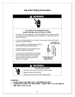
Page 3: ...2 Important Safety Information WARNING DO NOT USE A GROUND FAULT INTERRUPTER GFI A DEDICATED CIRCUIT IS REQUIRED 15 AMP FOR 1 3 Ton DS AND 20 AMP FOR 1 2 3 4 Ton DS...

Page 4: ...environment becomes dry and humid These temperatures and humilities are optimized for long term storage of wine The DS ducted systems are designed for both outdoor and indoor installation Back curved...

Page 5: ...CellarTec 1 3 TON DS 45X34X23 4500 380 1000 cu ft R134a 115V 60HZ 8A 140 CellarTec 1 2 TON DS 45X34X23 6500 490 1500 cu ft R134a 115V 60HZ 14A 170 CellarTec 3 4 TON DS 45X34X25 8500 750 2000 cu ft R1...

Page 6: ...ature surrounding the enclosure shall not exceed the temperature of the enclosure by more than 25 F No enclosure wall shall receive direct sun or strong wind Lighting shall be of low wattage with a ti...

Page 7: ...ady for use only after a certified refrigeration technician has properly installed the system Proper installation is critical Apex can only warrant the quality of the components The installation of th...

Page 8: ...the next step Connect wires in the outlet box of the condensing unit to the power lines Connect wires in the outlet box of the evaporator unit to the temperature controller and then connect the contro...

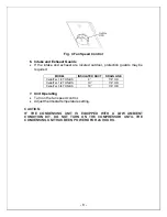
Page 9: ...UCT DRAIN LINE CellarTec 1 3 TON DS 8 7 8 OD CellarTec 1 2 TON DS 10 7 8 OD CellarTec 3 4 TON DS 10 7 8 OD 7 Unit Operating Turn on the fan speed control Adjust thermostat temperature setting CAUTION...

Page 10: ...required to reach the desired temperature will vary depending on the quantity of bottles temperature setting and surrounding temperature Allow 24 hours to stabilize the temperature for each new temper...

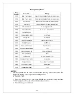
Page 11: ...side of the center blank key for approximately five seconds until screen matches the screen below 3 Press UP DOWN advance keys to select setup number press UP DOWN change keys to change settings 4 Pre...

Page 12: ...re Display 0 fahrenheit 1 celsius 0330 Daylight Savings 0 off 1 on 0340 Remote Air Sensor 0 no 3 indoor 0380 Indoor Dehumidification 0 no 0580 Min Compressor Off 5 five minutes off 0610 Min Cool Temp...

Page 13: ...system setup and set 670 2 to lock screen then exit 4 Temperature Setting 1 Enter the system setup and set 670 0 to unlock screen then exit 2 Press UP DOWN keys to modify temperature 3 Enter the syst...

Page 14: ...from flooding back to the compressor and aid oil returning to the compressor Charge the system after pipe brazing leak testing and evacuating Liquid must always be charged into the hide side It may us...

Page 15: ...r suction pressure by turning the hex nut 5 16 counter clockwise Fig 7 Liquid Filter Fig 8 Sight Glass Fig 9 Expansion Valve The line sizes and refrigerant charges are listed as follows MODEL LIQUID L...

Page 16: ...ceiver Discharge Compressor Suction 3 Liquid Line Suction Line 4 Pressure Control 3 Use of the adjustable pressure control if applicable for pump down Suction pressure setting Cut out 5 psig Cut in 25...

Page 17: ...Fig 12 Single Adjustable Pressure Control B Dual Control Fig 13 Dual Adjustable Pressure Control 4 Use of the encapsulated low pressure control if applicable Fixed suction pressure setting Cut in 32...

Page 18: ...h subcooling d High to normal suction pressure and high head pressure Low subcooling e High suction pressure and high head pressure Low subcooling f High suction pressure and high head pressure High s...

Page 19: ...pansion valve restricted m Both evaporator and condenser restricted n Liquid line restricted before receiver o Condenser restricted 8 Condensing Unit Troubleshooting Unit not running a Incorrect power...

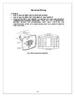
Page 20: ...E FOR THERMOSTAT AND SENSOR IF EQUIPPED WITH LOW AMBIENT CONDITION KIT USE LOW AMBIENT TEMPERATURE WIRING DIAGRAMS TURN OFF THE COMPRESSOR BEFORE POWER THE CONDENSING UNIT ONLY TURN ON THE COMPRESSOR...

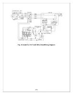
Page 21: ...20 Fig 16 CellarTec 1 3 Ton DS Electrical Wiring Diagram...

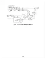
Page 22: ...21 Fig 17 CellarTec 1 2 Ton DS Electrical Wiring Diagram...

Page 23: ...22 Fig 18 CellarTec 3 4 Ton DS Wiring Diagram...

Page 24: ...23 Fig 19 Low Ambient Temperature CellarTec 1 3 Ton DS Electrical Wiring Diagram...

Page 25: ...24 Fig 20 Low Ambient Temperature CellarTec 1 2 Ton DS Electrical Wiring Diagram...

Page 26: ...25 Fig 21 Low Ambient Temperature CellarTec 3 4 Ton DS Wiring Diagram...

Page 27: ...need to be cleaned at least every 6 months Unplug the system or disconnect power Use a vacuum cleaner with an extended attachment to clean the coil when it is dusty or dirty Plug cooling system or re...

Page 28: ...re is 57 F and then the wine temperature is around 57 0 5 F The air is light enough to change so quickly that it maintains relatively constant average temperature that would prevent wine bottle temper...

Page 29: ...fresh air intake side c Check for excessive size d Check for installation location or increase setting e Clean condenser 7 Evaporator freezing up a Evaporator air flow restriction b Unit not stopping...

Page 30: ...high ambient temperatures or airflow restriction d Malfunctioning components a Add support to improve installation b Check fans cabinet washers tubing contact and loose screws c Check for airflow bloc...

Page 31: ...30 Customer Support If you still have problems please contact us at Apex 17631 South Susana Road Rancho Dominguez CA 90221 Tel 310 886 3332 Fax 310 886 3310 Email info groupapex com...

Page 32: ...ress or implied including any of fitness for a particular purpose In no event shall APEX be responsible for any consequential damages what is so ever Any modification of APEX products shall void this...

Page 33: ...LOSS OF TIME OR COMMERCIAL LOSS ANY OUTER DAMAGES WHETHER INCIDENTAL CONSEQUENTIAL OR OTHERWISE THIS WARRANTY IS EXCLUSIBE AND IS IN LIEU OF ALL OTHER WARRANTIES EXPRESSED OR INPLIED INCLUDING BUT NO...

Reviews: