background image

www.cellarcool.com | Page 17

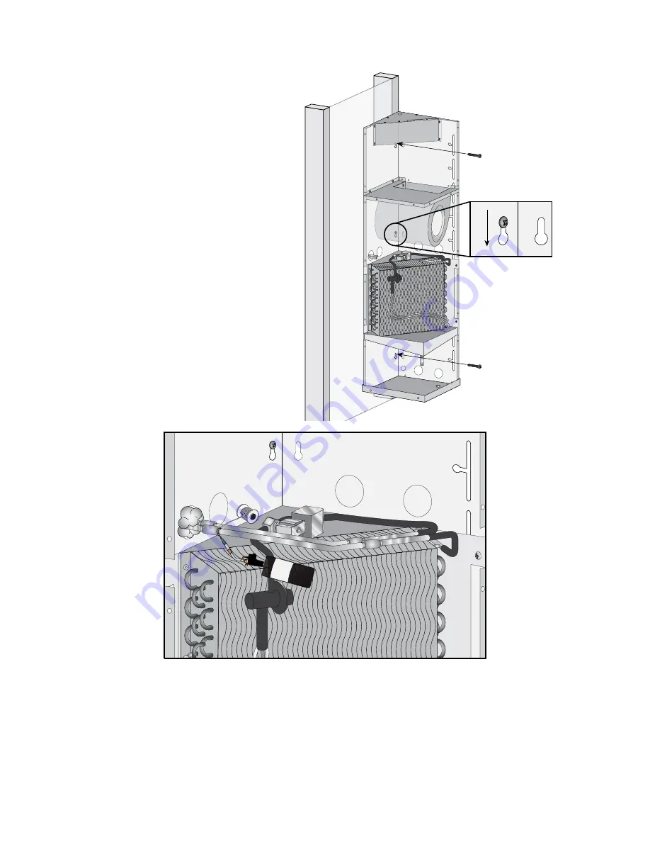
Secure the evaporator unit by installing a screw 

in both the upper and lower key holes that 

align with the pilot holes. Tighten all mounting 

screws once the evaporator unit has been set 

in place.

VERTICAL MOUNT INSTALLATION

Using proper practices and procedures for brazing refrigeration tubing: Purge nitrogen in to the system, 

braze the large tube of the line set to the suction line outlet and small tube to the liquid line inlet at the 

evaporator. Pressurize the system to 200 PSIG for 30 minutes to verify the system is sealed. Once complete, 

insulate the exposed suction line in the evaporator unit using Armaflex Insulation. 

Note: If the liquid line is going to sit in an area with direct sunlight or high ambient temperatures, 

insulation on the liquid line is recommended. DO NOT INSULATE  the suction line and liquid line 

with direct copper to copper contact. Each line needs to be insulated individually. Seal entry hole 

using expanding foam insulation.

Refer to page 26 for proper wiring of the twin 

system evaporator units.

Summary of Contents for HM&VM TWIN S

Page 1: ...92115 HM VM TWIN S TECH OWNERS MANUAL NOTICE To activate the split system warranty the installing certified HVAC R service tech must complete the split system warranty checklist and send back to Cella...

Page 2: ...s accurate CellarCool is not responsible for printing or clerical errors CellarCool reserves the right to make corrections or improvements to the information provided and to the related hardware at an...

Page 3: ...zontal Mount 10 Horizontal Mount Installation 11 Preparing the Installation Location Vertical Mount 15 Vertical Mount Installation 16 Condensing Unit Installation 20 Piping and Connecting Diagram 22 L...

Page 4: ...I Evaporator Unit Cover J Supply Air Panels K Access Panel L Thermal Expansion Valve M Liquid Line Solenoid N Drain Line Connection O Wiring Knock Outs Letter Label A Electrical Box B Key Hole C Blow...

Page 5: ...or Coil 6 Primary Condensate Drip Tray 7 Solenoid 8 Thermal Expansion Valve 9 Primary Line Set Knock Outs 10 Secondary Drip Tray Q R LEGEND Letter Label 11 Return Air Panels 12 Evaporator Unit Cover 1...

Page 6: ...ed circuit required Evaporator Coils 115V Condensing Unit 115V Evaporator Coils 115V Condensing Unit 208V 230V Single Phase Weight lbs 60 3500 x 73 5000 73 x2 AMPS Starting Running 2 5A 2 5A dBA 56 56...

Page 7: ...ed in page 39 Please read and review this manual carefully and keep it for future reference What Is the CellarCool Cooling System The CellarCool cooling system is a specialized refrigeration system de...

Page 8: ...options ordered are listed If any items listed on the packing slip do not match your order information contact CellarCool Customer Service immediately Check the Box for the following contents RECEIVIN...

Page 9: ...ly designed and constructed wine cellars Hire a professional wine storage consultant with a valid contractor s license to build your wine cellar If you encounter a problem with your CellarCool system...

Page 10: ...ned by the rate at which heat passes through the insulation The higher the R value the more resistant the insulation is to conducting heat Using higher R values in insulation will lower your operating...

Page 11: ...onment by capturing the warm air and replacing it with cool air Mounting the unit low in the room will result in a temperature variation in the room due to the unit s inability to draw warm air from t...

Page 12: ...he evaporator unit Make the same measurement on the wall with the origin at intersection of the horizontal and center line Using a saw cut out a small square followed by running the line set through t...

Page 13: ...nd Cap Drill two 5 32 pilot holes in the line intersections make sure they are 16 on center Screw in one of the provided 1 3 4 Hex Head screws in the right hole Install the evaporator unit by aligning...

Page 14: ...to the suction line outlet and small tube to the liquid line inlet at the evaporator Pressurize the system to 200 PSIG for 30 minutes to verify the system is sealed Once complete insulate the exposed...

Page 15: ...clamp around drain line Slide the drain line over the tube at the outlet of the drip tray Install the provided hose clamp on the drain line where the drain line is attached to the tube This will ensu...

Page 16: ...8 Phillips Pan Head screws For the 2500 3500 models remove at lease one supply and one return panel For the 5000 6500 models remove at least two return air panels and at least two supply air panels N...

Page 17: ...ough the hole Note There are six possible knock out holes to use for the line set Two entries are located on the frontal exterior of the evaporator unit Minimum Tools Needed Saw Screwdriver Level PREP...

Page 18: ...nit securing the secondary drip tray Drill three 5 32 pilot holes in the marks made on the center line Screw in one of the provided 1 3 4 Hex Head screws in the center hole Install the evaporator unit...

Page 19: ...ll tube to the liquid line inlet at the evaporator Pressurize the system to 200 PSIG for 30 minutes to verify the system is sealed Once complete insulate the exposed suction line in the evaporator uni...

Page 20: ...e dispense area Place hose clamp around the drain line Slide the drain line over the tube at the outlet of the drip trays Install the provided hose clamps where the drain line is attached to the tube...

Page 21: ...Phillips Pan Head screws FINALIZING VERTICAL MOUNT INSTALLATION For the 2500 3500 models remove at lease one supply and one return panel For the 5000 6500 models remove at least two return air panels...

Page 22: ...the evaporator units are wired together turned on and calling for cooling Connect a micron gauge directly to the pump blank off and start the pump to verify that it is capable of a 200 micron vacuum...

Page 23: ...ings Allow time for the temperature to register on the temperature meter and stabilize out this usually takes about a minute Compare the temperature of the liquid line with the condensing pressure con...

Page 24: ...Page 22 1 855 235 5271 TWS 092115 PIPING AND CONNECTING THE CR TO THE C...

Page 25: ...ith room temperature tap water 3 Place bottle probe securely into bottle as seen in Figure 1 4 Place bottle with probe level and to the side of the unit in your wine cellar 5 To assure a consistent te...

Page 26: ...ecure the wall mount bracket to the wall If routing the communication line through a wall connect the wires to the back of the control following the image above Connect the red wire to the upper termi...

Page 27: ...ale 2 pin connector in the electrical compartment This is the A unit The A unit contains the system control The B unit is controlled via the included control cable by the A unit Locate the desired kno...

Page 28: ...unit electrical compartment Attach the cable to 2 pin connector Make sure to follow the label marked Key Route the control cable from the A unit to the B unit Cut the wire to length Secure the cables...

Page 29: ...wer Liquid Line Solenoid Fan Capacitor Green S Black D Blue M Black F Brown R Blue V Black G Blue N Blue O 1 2 3 4 1 2 3 4 Green U 1 2 3 4 5 6 7 1 2 3 4 5 6 7 A B Black E 115V H Black C Green T Black...

Page 30: ...ck E Green R 1 2 3 4 5 6 7 1 2 3 4 1 2 3 4 5 6 7 1 2 3 4 Liquid Line Solenoid Blue P Blue Q Blower Fan Capacitor Black C Brown U Green S Blue K Black B 120V Green R Blue N Black F Blue L Blue M Green...

Page 31: ...6 7 120V Green R Blue N Black F Blue L Blue M Green T Black H Black G White J Blue O Black E 115V Hot Black C Green Black C Black B 1 2 3 4 1 2 3 4 A B 1 2 3 4 5 6 7 1 2 3 4 5 6 7 A B 1 2 3 4 5 6 7 8...

Page 32: ...1 2 3 4 5 1 2 3 4 5 H L FC F H L2 L1 1 2 3 4 5 COMP POTENTIAL RELAY LEVER CONNECTORS L1 LINE 1 L2 LINE 2 H HEATER H L HI LOW PRESSURE SWITCH F FAN FC FAN CYCLE SWITCH D O B RELAY HIGH PRESSURE SWITCH...

Page 33: ...ta History and start recording from the current time and temperature forward Temperatures displayed would reflect Air Sensor Temperatures from that point in time and beyond 3 The Hi Lo feature should...

Page 34: ...is automatically activated when the evaporator temp has reached a low temp of 26 and has sustained that temp for a period of five minutes During this cycle the compressor and condenser fans will turn...

Page 35: ...a minimum of three days before making any additional adjustments This will allow the cellar sufficient time to acclimate to the new setting Fof Humidity Management Enhancement This parameter is normal...

Page 36: ...ter the compressor turns off allowing moisture to be re evaporated into the cellar Anti Short Cycle The Anti Short Cycle ensures that the unit will remain off for a period of 5 minutes after the unit...

Page 37: ...n line to see if it is above the waterline if draining into a vessel Quarterly 1 Use a vacuum with brush attachment to clean coils Be careful not to crush coil fins when cleaning Annually 1 Inspect fo...

Page 38: ...l is very dirty use a spray bottle with a small amount of liquid dish washing detergent Spray coil let set for 5 min then flush with fresh water Remove blockage Call a service tech to troubleshoot Che...

Page 39: ...55 235 5271 Call Customer Service at 1 855 235 5271 Solution Call Customer Service at 1 855 235 5271 Call Customer Service at 1 855 235 5271 Call Customer Service at 1 855 235 5271 Call Customer Servi...

Page 40: ...stomer Service 1738 E Alpine Ave Stockton CA 95205 www CellarCool com Email support cellarcool com Phone 209 466 9463 US Toll Free 1 855 235 5271 Fax 209 466 4606 CellarCool offers accessories to enha...

Page 41: ...he Split Startup Checklist is approved Purchaser will be sent activation approval documents and will start receiving the benefits of the Limited Warranty throughout the warranty period If the Split St...

Page 42: ...serial number which is evidence that the Product is within the Limited Warranty Period must be presented by the End User to CellarCool in order to obtain limited warranty service 7 This limited warran...

Page 43: ...CellarCool Customer Service to arrange for replacement under the warranty guidelines When a claim for warranty is submitted for a condenser skid the End User must purchase a new condenser skid from Ce...

Page 44: ...include the Invoice from the Independent Certified HVAC R Technician and the written report of the findings The Owner will become responsible for payment directly to CellarCool for all charges incurre...

Page 45: ...to 4 00 p m PST The Customer Service representative will be able to assist you with your questions and warranty information more effectively if you provide them with the following 1 The model and ser...

Page 46: ...TWS 092115 CellarCool 1738 E Alpine Ave Stockton CA 95205 1 855 235 5271 www cellarcool com...

Reviews: