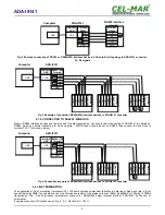
Fig 2. Example connection of RS422 or RS485(4W) interface devices in Point-to-Point topology to ADA-I9141 converter;
Tx, Rx signals
Fig 3. Example of connection RS485(4W) interface devices to ADA-I9141 converter
4.1.2. CONNECTION TO RS485 2-WIRE BUS
Most of RS485 interface devices use two-wire bus for data transmission. You should check the setting of ADA-I9141 to operate on
RS485 2-wire bus before connecting to 2-wire network – MODE switch should be set on RS485, then connect the bus wires to
terminal TX+, TX- as shown below.
Fig 4. Connection example of RS485(2W) interface devices to ADA-I9141 converter
4.2. LINE TERMINATION
The application of Line Termination (terminator) Rt = 120 ohms will reduce electrical reflection in data line at high baud rate. It is not
needed below 9600Bd. You should use the Line Termination resistor if the distance is over 1000m @ 9600Bd or 700m @ 19200Bd
transmission. The Line Termination (terminators) connect to RS485/422 screw terminal block of ADA-I9141 by the use of
screwdriver.
Example connection of Rt are shown on Fig. 2, 3, 4 . Resistor Rt = 120
W
.
5
ADA-I9141
RS422 interface
device
Terminal
RS422
Tx+
Tx-
GND
Rx+
Rx-
Rt
Rt
Rx+
Rx-
GND
Tx+
Tx-
USB
Interface
USB
Terminal
RS422
ADA-I9141
USB
Computer
RS485 (4W)
Terminal
GND
T
e
rm
in
al
R
S
4
85
(4
W
)
T
x-
G
N
D
R
x+
R
x-
T
er
m
in
a
l
R
S
48
5(
4W
)
T
x+
T
x-
G
N
D
R
x+
R
x-
T
e
rm
in
al
R
S
48
5(
4W
)
T
x+
T
x-
G
N
D
R
x+
R
x-
Rt
T
x+
R
t
Rt
R
t
Rx+
Rx-
Tx+
Tx-
USB
ADA-I9141
Interface
USB
USB
Computer
GND
RS485 (2W)
Terminal
T
e
rm
in
al
R
S
48
5(
2W
)
T
x-
/
B
G
N
D
R
x+
R
x-
T
e
rm
in
al
R
S
4
85
(2
W
)
T
x+
/
A
T
x-
/
B
G
N
D
R
x+
R
x-
T
er
m
in
a
l
R
S
48
5(
2W
)
T
x+
/
A
T
x-
/
B
G
N
D
R
x+
R
x-
T
x+
/
A
R
t
Rt
Rx+
Rx-
Tx+
Tx-
USB
ADA-I9141
Interface
USB
USB
Computer


