2.2. DESCRIPTION
ADA-I9141 converts
USB to RS-485/RS-422 standard without interference of data format and it is automatically detect by PC system
after connecting to USB network (Plug&Play device). ADA-I9141 uses data transmission lines Rx, Tx & GND (signal ground) for
communication with other RS485/422 devices.
This converter doesn't required external power supply (it is powered from USB bus) and it uses asynchronous baud rate up to 921,3
kbps (drivers for STANDARD baud rate) / 1500000 bps (drivers for PROFIBUS baud rate).
A-type USB Mail plug (or USB cable with A-type connector) enables simple connection to computer and on other side simple
connection the RS485/422 Bus provide plug-in screw terminal block.
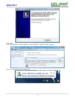
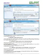
Together with the ADA-I9141 we provide the drivers, which after installation, create in operating system additional COM port on the
next free number e.g. COM3. It can be use as standard COM port but it isn't hardware port but virtual, create in Windows system. This
is the reason why some applications running in DOS and use this port, can operate improperly.
3. CONFIGURATION
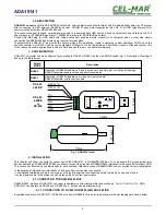
ADA-I9141 converter can be configured for operating in RS485 or RS422 by the use MODE switch (fig.1). Description of setting is
shown in the table below.
Switch
MODE
Description
RS485
Operating in RS485 standard on 2 and 4-wire bus in point-to-point or multi-point topology.
RS485 transmitter enable only during data transmission
RS422
Operating in RS422 standard on 4-wire bus in point-to-point.
RS422 transmitter continuously enable.
Fig 1. ADA-I9141 view
4. INSTALLATION
This chapter will show you correctly connection of the ADA-I9141 to RS-485/RS-422 Bus. To compensate the ground potential of
devices operating on RS485/RS422 Bus you should connect the grounds of RS485/RS422 interfaces to the converter terminals GND.
This connection should be done individually for each systems if standard wiring of RS485/RS422 bus not provide correct transmission.
In the purpose of disruptions minimization of influence from environment you should :
- use shielded twisted-pair cable in the system, of which it is possible to connect the shield to ground on one end of cable,
- lay the signals cable in the distance no short than with 25 cm from power cable.
4.1. CONNECTION TO RS485/RS422 BUS
RS485/RS422 interface of ADA-I9141 converter is available on screw terminal block described as: Tx+/A, Tx-/B, Rx+, Rx-, GND.
ADA-I9141 can operate on RS422 bus or RS485 bus - both bus need suitable wiring.
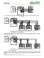
4.1.1. CONNECTION TO RS422 OR RS485 (4W) BUS 4-WIRE
Examples connection of ADA-I9141 to RS422 4-wire bus or RS485(4W) in point-to-point and multi-point topology are shown below.
4
ADA-I9141
TX
RX
485
422
MODE
ADA-I9141
TX+/ A
TX-/ B
RX+
RX-
GND
®
77mm
68mm
31
m
m
24
,5
m
m
TX-
RX+
RX-
GND
DATA+ / A
DATA- / B
TX+
RS-485
2-WIRE
RS-485
4-WIRE
or
RS-422


