background image

8. IMPLEMENTATION OF THE MODBUS-RTU PROTOCOL

ADA-4040PC8 protocol converter allows connecting controllers with the JCT-ASCII protocol as SLAVE to the RS485 bus MODBUS-

RTU. The length of RS485 bus can be extended (next segments of 1200 m) by the use of ADA-4040 repeaters or ADA-4044H HUBs 

RS485.

The MODBUS-RTU protocol used for communication between ADA-4040PC8 converters and SCADA-type system or PLC controller 

enable easy integration of JCT controllers in existing automation systems.

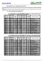
8.1. TABLE OF MODBUS-RTU ADDRESSES

8.1.1. REGISTERS OF ACTUAL MEASUREMENTS VALUES OF JCT CONTROLLER, READUOT 
BY FUNCTION 04 [3 X - REFERENCES] INPUT REGISTERS

No.

Modbus 

registers 

Address 3X 

Registers 

for the 

Reading 

Range 

of data 

Range of 

Modbus 

data 

DW divisor 

of the value 

of the Modbus 

register 

Parameter 

symbol

Parameter description 

1.

30121 

Read

0.0~2.000

0~2000

1000

PV

Cp PV value

2.

30122 

Read

0~1500

0~1500

1

PO

O2 mV PV value

3.

30123 

Read

0.0~999.9

0~9999

10

PT

Temperature PV value

4.

30124 

Read

0.0~2.000

0~2000

1000

SV

Cp SV value

5.

30125 

Read

-2.000~2.000 -2000~2000

1000

CC

Cp compensation value

6.

30126 

Read

-100~100

-100~100

1

TC

Temperature compensation

7.

30127 

Read

-100~100

-100~100

1

MC

O2 mV compensation value

8.

30128 

Read

10.00~50.00 1000~5000

100

CO

Carbon monoxide value

9.

30129 

Read

0~1300

0~1300

1

TA

Safety temperature value

10. 30130 

Read

0~1300

0~1300

1

TM

Enriching gas start temperature

11. 30131 

Read

1~1000

1~1000

1

KP

Proportion band value

12. 30132 

Read

1~1000

1~1000

1

TI

Integral factor value

13. 30133 

Read

0~1000

0~1000

1

TD

Derivative factor value

14. 30134 

Read

0.0~2.000

0~2000

1000

EV

Event value

15. 30135 

Read

0,1

0,1

1

CM

Communication mode

16. 30136 

Read

0,1

0,1

1

AM

Automatic/manual mode

17. 30137 

Read

0,1

0,1

1

SR

Execution/stop mode

18. 30138 

No Read

0~100

0~100

1

AO

Carrier control output (out2)

19. 30139 

No Read

0,1

0,1

1

ED

Prompt of finishing

20. 30140 

No Read

0~100

0~100

1

OT

Enriching control output (out1)

8.1.2. REGISTERS OF ACTUAL MEASUREMENTS VALUES OF JCT CONTROLLER, READOUT 
BY FUNCTION 03 OR SAVED BY FUNCTION 06 [4 X - REFERENCES] HOLDING REGISTERS 

No.

Modbus 

registers 

Address 4X 

Registers 

for the 

Reading/

Writing

Range 

of data 

Range of 

Modbus 

data 

DW factor 

of Modbus 

register value

Parameter 

symbol

Parameter description

1.

40121 

Read

0.0~2.000

0~2000

1000

PV

Cp PV value

2.

40122 

Read

0~1500

0~1500

1

PO

O2 mV PV value

3.

40123 

Read

0.0~999.9

0~9999

10

PT

Temperature PV value

4.

40124 

R/W

0.0~2.000

0~2000

1000

SV

Cp SV value

5.

40125 

R/W

-2.000~2.000 -2000~2000

1000

CC

Cp compensation value

6.

40126 

R/W

-100~100

-100~100

1

TC

Temperature compensation

7.

40127 

R/W

-100~100

-100~100

1

MC

O2 mV compensation value

8.

40128 

R/W

10.00~50.00 1000~5000

100

CO

Carbon monoxide value

9.

40129 

R/W

0~1300

0~1300

1

TA

Safety temperature value

10. 40130 

R/W

0~1300

0~1300

1

TM

Enriching gas start temperature

11. 40131 

R/W

1~1000

1~1000

1

KP

Proportion band value

12. 40132 

R/W

1~1000

1~1000

1

TI

Integral factor value

13. 40133 

R/W

0~1000

0~1000

1

TD

Derivative factor value

14. 40134 

R/W

0.0~2.000

0~2000

1000

EV

Event value

15. 40135 

R/W

0,1

0,1

1

CM

Communication mode

16. 40136 

R/W

0,1

0,1

1

AM

Automatic/manual mode

17. 40137 

R/W

0,1

0,1

1

SR

Execution/stop mode

18. 40138 

Write

0~100

0~100

1

AO

Carrier control output (out2)

19. 40139 

Write

0,1

0,1

1

ED

Prompt of finishing

20. 40140 

Write

0~100

0~100

1

OT

Enriching control output (out1)

12

ADA-4040PC8 

Summary of Contents for ADA-4040PC8

Page 1: ...User manual ADA 4040PC8 VIRAP JCT ASCII to MODBUS RTU Protocol Converter 1 ADA 4040PC8 Copyright 2001 2021 CEL MAR io_ada 4040pc8_v1 02_en...

Page 2: ...ING 7 5 CONFIGURATION 7 5 1 OPERATION MODE 7 5 2 CONFIGURATION BY USING ADACONFIG 8 5 3 FIRMWARE UPDATE 9 5 4 EMERGENCY FIRMWARE UPDATE 10 5 5 FACTORY DEFAULT 10 6 DATA TRANSMISSION DIAGNOSTICS 10 7 O...

Page 3: ...the power supply circuit voltage Do not carry out the assembly or disassembly of the device if it is enabled This may result to short circuit and damage the device The device can not be used for appli...

Page 4: ...reliability ADA 4040PC8 supports asynchronous data transmission with baudrate up to 230 4 kbps through two or one pair of twisted pairs connected to screw terminals The device for its operation uses...

Page 5: ...e the rail upper part of the cover then press bottom part it hear characteristic Click sound 3 2 COMPUTER CONNECTION To connect ADA 4040PC8 to computer is needed additional converter e g ADA I9141 USB...

Page 6: ...bus and JCT1 controller to ADA 4040PC8 6 ADA 4040PC8 RS485 RS422 connector RS485 4W BUS 19200Bd 8 N 1 MODBUS RTU MASTER MODBUS RTU DEVICE SLAVE 1 MODBUS RTU GND Rt Rt Rx Rx Tx A Tx B RS485 2W 9600Bd 8...

Page 7: ...the LEDs Tx and Rx should blink ATTENTION AT BAUD RATE ABOVE 38 4 KBPS OF THE TX DIODE MORE POORLY WILL LIGHT RX DURING THE DATA TRANSFER 4 1 DESCRIPTION OF SIGNALLING LEDS LED Description PWR Signal...

Page 8: ...nd in the field Address enter the MODBUS RTU converter address from the RTU port 4 setting the address of the connected VIRAP JCT device to the JTC RS485 port Mapped Address field range 1 99 In the se...

Page 9: ...e the software delivered by manufacturer The Select File window will open fig below and select the bin file then click Open software will be load to ADAConfig buffer storage and will be checked If the...

Page 10: ...tes 4 4 Set SW1 microswitch mode as in the table below SW1 1 SW1 2 OFF ON Disconnect the power and after while connect again the power After that will be loaded the factory default setting to the conv...

Page 11: ...IMPLEMENTATION OF THE MODBUS RTU PROTOCOL MODBUS protocol frames with the CRC error are rejected by the converter JCT ASCII protocol frames with a checksum error are rejected by the converter In case...

Page 12: ...000 0 2000 1000 EV Event value 15 30135 Read 0 1 0 1 1 CM Communication mode 16 30136 Read 0 1 0 1 1 AM Automatic manual mode 17 30137 Read 0 1 0 1 1 SR Execution stop mode 18 30138 No Read 0 100 0 1...

Page 13: ...saved to regular type variable float and then divide it by the DW factor Fragment of code in C language VS6 0 presenting above algorithm short int siMeasureReg float fMeasureVal fMeasureVal float siMe...

Page 14: ...ave values to 16 bits of the MODBUS register of the ADA 4040PC8 converter The saved value in the register is processed and transmitted to the JCT controller MODBUS registers are in the format of the 1...

Page 15: ...1 Byte 40 01 to F7 01 Code of the function 1 Byte 86 02 Error code 1 Byte 01 unknown function 02 unknown data address 03 unknown amount of data 04 JCT controller is not responding is not connected or...

Page 16: ...ate from RTU of ports RS485 RS422 TX yellow LED date transmission through RTU of ports RS485 RS422 Electrical Parameters Power requirements 10 24 30 V DC Power Cable Recommended length of power cable...

Page 17: ...data transmission converters with interface RS232 RS485 RS422 USB Current Loop Fibre Optic Converters and Ethernet or Wi Fi Please contact us to tell how you like our products and how we can satisfy y...

Reviews: