background image

www.usaprocom.com

200125-01A

24

Problem

Possible Cause

Corrective Action

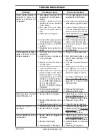
When  ignitor  button  is 

pressed  in,  there  is  no 

spark at ODS/pilot

1. Ignitor  electrode  is  posi-

tioned  wrong.  Ignitor  elec-

trode is broken.

2. Ignitor electrode is not con-

nected to ignitor cable.

3. Ignitor  cable  is  pinched  or 

wet.

4  Broken ignitor cable.

5. Bad piezo ignitor.

6. Low battery.

1. Replace electrode.

2. Replace ignitor cable

3. Free ignitor cable if pinched 

by any metal or tubing. Keep 

ignitor cable dry.

4. Replace ignitor cable.

5. Replace piezo ignitor.

6. Replace battery.

TROUBLESHOOTING

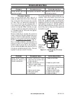
NG

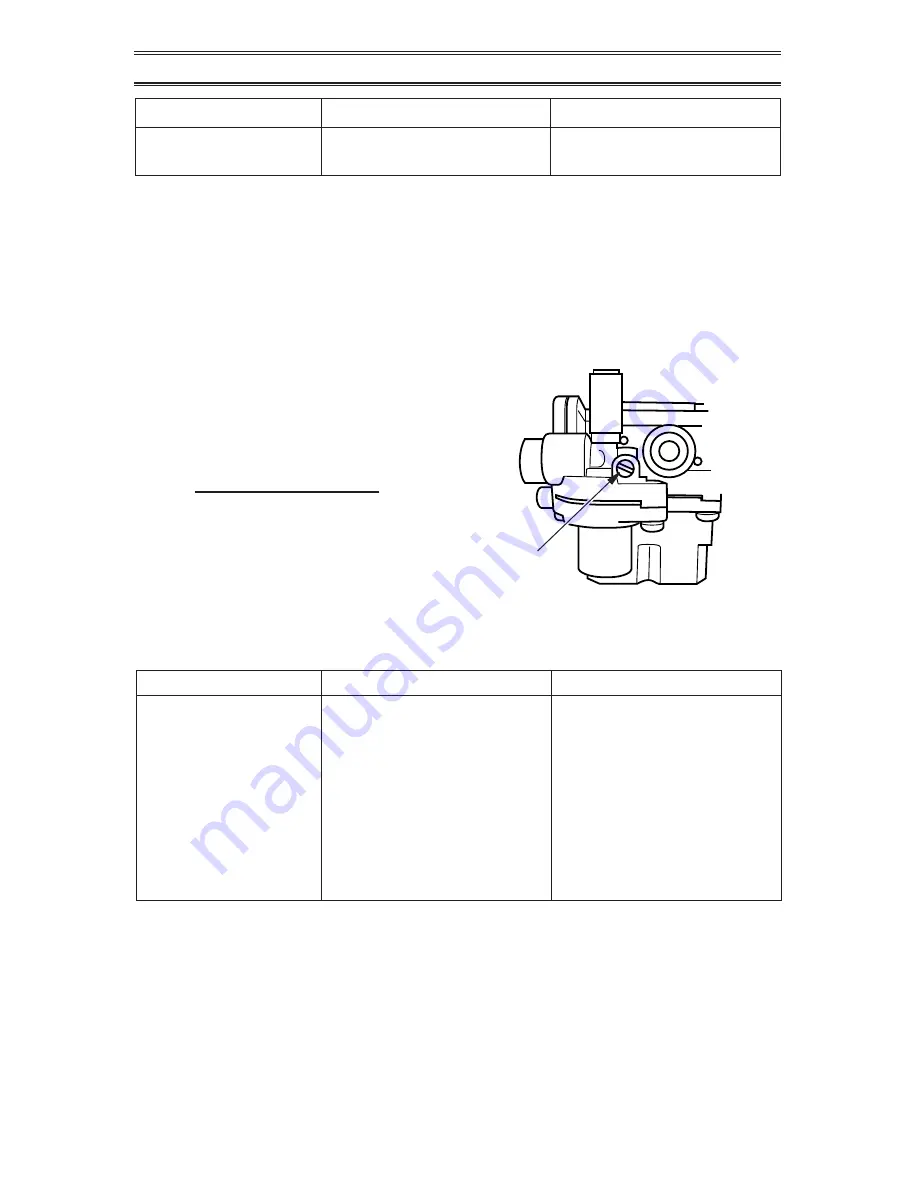
Figure 31 - Gas Regulator Pressure 

Switch

Pressure 

Switch 

Set Screw

Pressure Switch

When  using  natural  gas  (NG),  there  is  a 

pressure switch that acts to turn off the gas 

flow to the pilot if the inlet pressure exceeds 

9.5" WC. This is to prevent the operation of 

the  unit  on  the  wrong  gas  (propane/LP).  If 

your natural gas supply exceeds 9" WC the 

unit will not operate. Either contact your gas 

supplier to check and adjust the inlet pressure 

or a qualified service technician can bypass 

the pressure switch.
Before  attempting  to  bypass  the  pressure 

switch, make sure the type of gas being used 

is correct. Check to make sure the connection 

fitting is in the correct inlet on the regulator. 

Refer to 

Connecting to Gas Supply

, page 11.

Only a qualified installer should bypass the 

pressure  switch.  To  bypass  the  pressure 

switch locate the set screw on the regulator. 

Use a small flat bladed screw driver to turn the 

set screw counterclockwise 2 turns. This will 

bypass the pressure switch function.

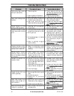
Problem

Possible Cause

Corrective Action

Using  natural  gas  and 

pilot will not light.

Inlet pressure exceeds 9"  WC. Bypass  pressure  switch.  See 

instructions below.

The entire gas delivery piping including con-

nections  inside  the  heater  should  be  leak 

tested  by  the  qualified  installer. After  leak 

testing the qualified installer should light the 

appliance. Refer to the correct flame pattern 

as illustrated on page 21. All flame patterns 

should be safely inside the product. If for any 

reason they are not, stop use of the appliance 

and call for repairs.

Summary of Contents for CRHSD25RTA

Page 1: ...e or use gasoline or other flammable va pors and liquids in the vicinity of this or any other appliance WHAT TO DO IF YOU SMELL GAS Do not try to light any appliance Do not touch any electrical switch do not use any phone in your building Immediately call your gas supplier from a neighbor s phone Follow the gas supplier s instructions If you cannot reach your gas supplier call the fire department ...

Page 2: ...tecombustionandventilationairmustbeprovided Refer to Air For Combustion and Ventilation section on page 7 of this manual WARNING Improper installation adjustment al teration service or maintenance can cause injury or property damage Refer to this manual for correct in stallation and operational procedures For assistance or additional information consult a qualified installer service agency or the ...

Page 3: ...e with heart or lung disease or anemia those under the influ ence of alcohol and those at high altitudes NATURALAND PROPANE LP GAS Natural and Propane LP gas are odorless An odor making agent is added to the gas The odor helps you detect a gas leak However the odor added to the gas can fade Gas may be present even though no odor exists WARNING Any change to this heater or its controls can be dange...

Page 4: ...hould service and repair heater 11 Operating heater above elevations of 4 500 feet could cause pilot outage 12 To prevent performance problems do not use propane LP fuel tank of less than 100 lbs capacity 13 Do not use this heater as a wood burning heater Use only the logs provided with the heater 14 Solid fuels should not be burned in a heater in which a vent free log set is installed Do not use ...

Page 5: ...rposes of input adjustment Maximum 9 Maximum 14 Minimum 5 Minimum 11 Heater Dimensions HxWxD 28 31 25 75 16 Carton Dimensions HxWxD 30 31 28 35 17 91 Stove Weight 62 7 lbs Shipping Weight 71 5 lbs LOCAL CODES Install and use heater with care Follow all local codes In the absence of local codes use the latest edition of The National Fuel Gas Code ANSI Z223 1 NFPA 54 Available from American National...

Page 6: ...water vapor does not become a problem 1 Be sure the heater is sized properly for the application including ample combustion air and circulation air 2 If high humidity is experienced a dehu midifier may be used to help lower the water vapor content of the air 3 Do not use an unvented room heater as the primary heat source UNPACKING 1 Remove top inner pack 2 Tilt carton so that heater is upright 3 R...

Page 7: ...y efficient your home needs to breathe Fresh air must enter your home All fuel burning ap pliances need fresh air for proper combustion and ventilation Exhaust fans fireplaces clothes dryers and fuel burning appliances draw air from the house to operate You must provide adequate fresh air for these appliances This will insure proper venting of vented fuel burning appli ances WARNING This heater sh...

Page 8: ...ntrolled power vent Heated air entering the attic will activate the power vent Rework worksheet adding the space of the adjoining unconfined space The combined spaces must have enough fresh air to supply all appliances in both spaces Figure 2 Ventilation Air from Inside Building Or Remove Door into Adjoining Room Option 3 Ventilation Grills Into Adjoining Room Option 2 Ventilation Grills Into Adjo...

Page 9: ...o discolor IMPORTANT Vent free heaters add mois ture to the air Although this is beneficial installing heater in rooms without enough ventilation air may cause mildew to form too much moisture See Air for Combustion and Ventilation page 7 Figure 4 Minimum Clearance to Wall and Ceiling CHECK GAS TYPE Be sure your gas supply is right for your heat er Otherwise call dealer where you bought the heater...

Page 10: ...recompleting the installation and operating this appliance 1 Theinletregulatoriscolorcodedforidentifica tionofthecorrectgastype Blueisforpropane LP gas and yellow is for natural gas 2 The inlet regulator requires a 3 8 NPT threaded fitting Apply a thread sealant that is rated for use with the type of gas that is being used 3 Determine the type of gas that will be used bytheappliance Ifyourgastypei...

Page 11: ...on must include an equipment shutoff valve union and plugged 1 8 NPT tap Locate NPT tap within reach for test gauge hook up NPT tap must be upstream from heater see Figure 8 page 13 IMPORTANT Install an equipment shutoff valve in an accessible location The equip ment shutoff valve is for turning on or shutting off the gas to the appliance WARNING A qualified ser vice technician must connect heater...

Page 12: ...ointing the vent down protects it from freezing rain or sleet For both gas types install sediment trap in supply line as shown in Figure 8 Place sedi ment trap where it is within reach for cleaning Place sediment trap where trapped matter is not likely to freeze Asediment trap traps mois ture and contaminants This keeps them from going into heater controls If sediment trap is not installed or is i...

Page 13: ...regulator 2 Cap off open end of gas pipe where equip ment shutoff valve was connected 3 Pressurize supply piping system by either opening propane LP supply tank valve for propane LP gas or opening main gas valve located on or near gas meter for natural gas or using compressed air 4 Check all joints of gas supply piping sys tem Apply noncorrosive leak detection fluid to all joints If bubbles form t...

Page 14: ...Failure to posi tion the parts in accordance with these diagrams or failure to use only parts specifically approved with this heater may result in property damage or personal injury CAUTION After installation and periodically thereafter check to ensure that no flame comes in contact with any log Withtheheatersettohigh check toseeifflamescontactanylog If so reposition logs according to the log inst...

Page 15: ...ly logs supplied with heater INSTALLING BATTERIES CAUTION Donotmixoldand new batteries Do not mix alka line standard carbon zinc or rechargeable nickel cadmium batteries Do not dispose of batteries in fire batteries may explode or leak Batteries are included Remove batteries when depleted Install replace the batteries according to the type and quantity stated in table below Do not mix old and new ...

Page 16: ... technician Force or attempted repair may result in a fire or explosion D Do not use this appliance if any part has been under water Immediately call a qualified service technician to inspect the appliance and to replace any part of the control system and any gas control which has been under water AA AA AA AAA AAA AA REMOTE OFF ON LEARN Figure 18 Installing Batteries in Remote Control and Receiver...

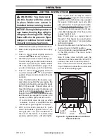
Page 17: ...epairs Until repairs are made light pilot with match If control knob does not pop up when released contact a qualified service technician or gas supplier for repairs 6 With control knob pressed in push down and release ignitor button This will light pilot The pilot is attached to the rear of the burner If needed keep pressing ignitor button until pilot lights Note If pilot does not stay lit refer ...

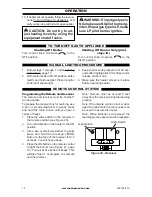
Page 18: ...PPLIANCE MANUAL LIGHTING PROCEDURE LEARN REMOTE OFF ON Figure 20 Receiver REMOTE CONTROL SYSTEM Slide Switch Learn Button Programming the Remote and Receiver The remote and receiver must be learned to one another To prepare the receiver box for learning use a pen or small screwdriver to gently press and hold the learn button until you hear 3 series of beeps 1 Place the slide switch on the receiver...

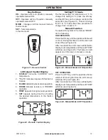
Page 19: ...on Figure 24 Manual Mode in OFF Operation Setting F C Scale The factory setting for temperature is F To change this setting to C press the ON key and the OFF key on the remote control at the same time see Figure 21 This will change from F to C Follow this same procedure to change from C back to F Manual Function To operate the system in the manual MODE do the following ON OPERATION Press the ON ke...

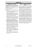
Page 20: ...sired Room Temperature The remote control system can control the thermostat when the transmitter is in the THERMO mode The word ROOM must be displayed on the screen To set the THERMO MODE and desired room temperature 1 Press the MODE key until the LCD screen shows the word ROOM The remote is now in the thermostatic mode 2 Press and hold the SET key until the de sired set temperature is reached The...

Page 21: ...your heater could pro duce increased levels of carbon monoxide If the burner flame pattern shows yellow tipping follow instructions at bottom of this page Notice Do not mistake orange flames with yellow tipping Dirt or other fine particles enter the heater and burn causing brief patches of orange flame Approx 3 6 Above Top of Logs More Than 8 Above Top of Logs Approx 3 6 Above Top of Logs More Tha...

Page 22: ...er located at the end of the burner tube again Remove any large particles of dust dirt lint or pet hair with a soft cloth or vacuum cleaner nozzle 5 Blow air into the primary air holes on the injector holder 6 In case any large clumps of dust have now been pushed into the burner Repeat steps 3 and 4 CARE AND MAINTENANCE WARNING Turn off heater and let cool before servicing CAUTION You must keep co...

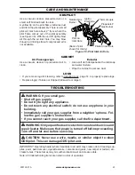
Page 23: ...pilot shown for clarity Pilot Air Inlet Hole Natural Gas Burner Propane LP Gas Burner Thermocouple Pilot Air Inlet Hole Ignitor Electrode TROUBLESHOOTING WARNING If you smell gas Shut off gas supply Do not try to light any appliance Do not touch any electrical switch do not use any phone in your building Immediately call your gas supplier from a neighbor s phone Fol low the gas supplier s instruct...

Page 24: ... gas supplier to check and adjust the inlet pressure or a qualified service technician can bypass the pressure switch Before attempting to bypass the pressure switch make sure the type of gas being used is correct Check to make sure the connection fitting is in the correct inlet on the regulator Refer to Connecting to Gas Supply page 11 Only a qualified installer should bypass the pressure switch ...

Page 25: ... touching thermocouple which allows thermocouple to cool caus ing pilot flame to go out This problem could be caused by one or both of the following A Low gas pressure B Dirty or partially clogged ODS pilot 6 Thermocouple damaged 7 Control valve damaged 1 Press in control knob fully 2 After ODS pilot lights keep control knob pressed in 30 seconds 3 Fully open equipment shutoff valve 4 Hand tighten...

Page 26: ...justafter burner is lit or shut off 1 Metal is expanding while heating or contracting while cooling 1 This is common with most heaters If noise is exces sive contact qualified ser vice technician White powder residue forming within burner box or on adjacent walls or furniture 1 When heated the vapors from furniture polish wax carpet cleaners etc turn into white powder residue 1 Turn heater off whe...

Page 27: ... malfunctioning Type of gas used Propane LP or Natural gas NG Purchase date Usually we will ask you to return the defec tive part to the factory PARTS NOT UNDER WARRANTY Contact authorized dealers of this product If they can t supply original replacement part s call Customer Service toll free at 1 866 573 0674 for referral information When calling Customer Service have ready Model number of your h...

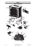
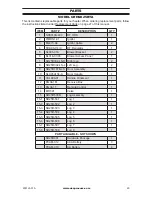
Page 28: ...www usaprocom com 200125 01A 28 PARTS MODEL CRHSD25RTA RE MO TE OF F ON LE AR N TEMP PILO T OFF ON 1 9 4 12 15 1 15 6 15 2 15 3 15 4 15 7 15 8 15 5 14 13 6 10 8 11 5 11 7 10 3 2 ...

Page 29: ...acket 2 6 BL016 07 03 Blower Access Panel 1 7 SD25R302 LS R Right Leg 2 8 SD25R302 LS L Left Leg 2 9 SD25R107B LS Door Assembly 1 10 SLU35A134 A Door Handle 1 11 VCL008 01 Handle Ornament 1 12 RG04 1M Receive Box 1 13 RG04 1T Remote Control 1 14 MRT 01 Valve 1 15 SD25R500B Log Assembly 1 15 1 SD25R 501 Log 1 1 15 2 SD25R 502 Log 2 1 15 3 SD25R 503 Log 3 1 15 4 SD25R 504 Log 4 1 15 5 SD25R 505 Log ...

Page 30: ...ctions furnished with the unit WHAT IS NOT COVERED This warranty does not apply to parts that are not in original condition because of normal wear and tear or parts that fail or become damaged as a result of misuse accidents lack of proper maintenance or defects caused by improper installation Travel diagnostic cost labor transportation and any and all such other costs related to repairing a defec...

Page 31: ...o use nin gún teléfono en el edificio Llame inmediatamente a su proveedor de gas des de el teléfono de algún vecino Siga las instruccio nes del proveedor de gas Si no puede localizar al proveedor de gas llame al departamento de bomberos La instalación y el servicio deben ser realizados por personal calificado una agencia de servicio o el proveedor de gas ADVERTENCIA Este aparato está equipado para...

Page 32: ...as necesarias para garantizar que hay suficiente aire para la combustión y ventilación Consulte la sección Aire para combustión y ventilación en la página 38 de este manual ADVERTENCIA La instalación ajuste alteración servicio o mantenimiento inadecuados pueden pro vocar lesiones o daños a la propiedad Consulte este manual para conocer los procedimientos correctos de instalación y de operación Par...

Page 33: ...azadas perso nas con enfermedades del corazón de los pulmones o anemia aquellas bajo la influen cia del alcohol y aquellas a grandes altitudes Gas natural y gas propano LP el gas na tural y gas propano LP son gases inodoros Al gas propano se le agrega un agente con olor El olor le ayuda a detectar las fugas de gas Sin embargo el olor que se añade al gas puede desvanecerse Es posible que haya gas p...

Page 34: ...n las paredes y los muebles adyacentes SEGURIDAD 8 Siempre haga funcionar el calentador con las perillas de control del piloto PILOT o de encendido ON en posiciones fijas Nunca coloque la perilla de control entre las dos posiciones ya que puede haber una mala combustión y mayores niveles de monóxido de carbono 9 No use este calentador si alguna de sus partes estuvo sumergida en agua Llame inmediat...

Page 35: ...eños está diseñado para no producir humo Si pareciera que los leños producen humo apague el ca lentador y llame a un técnico calificado Nota durante el primer uso es posible que haya un poco de humo debido al curado de los leños y a la combustión de los residuos de fabricación 18 No haga funcionar el calentador si alguno de los leños está roto No haga funcionar el calentador si alguno de los leños...

Page 36: ...nstale y use el calentador con cuidado Siga todaslasnormaslocales Afalta de normasloca les utilice la última edición del Código Nacional de Gas Combustible ANSI Z223 1 NFPA 54 Disponible en American National Standards Institute Inc 1430 Broadway New York NY 10018 EE UU National Fire Protection Association Inc Batterymarch Park Quincy MA 02269 EE UU Nota este calentador esta diseñado para operar si...

Page 37: ...e que el calentador tenga el tamaño adecuado para la aplicación incluidas la combustión y la circulación adecuadas del aire 2 Si hay humedad elevada se puede utilizar un deshumidificador para ayudar a reducir el contenido de vapor de agua del aire 3 No utilice un calentador de habitación sin ventilación como fuente principal de calefacción DESEMPAQUE 1 Retire la parte superior del empaque interno ...

Page 38: ...os ADVERTENCIA Este calen tador no se debe instalar en una habitación o espacio a menos queelvolumenrequeridodeaire de combustión en interiores es proporcionada por el método descrito en el Código Nacio nal de Gas Combustible ANSI Z223 1 NFPA 54 el Fuel Gas Code Internacional o aplicable códigos locales ADVERTENCIA Silazonaen la que la estufa se puede operar no cumple con el volumen re querido de ...

Page 39: ...e aire Espacio transitado ventilado Al espacio transitado Al ático AIRE PARA COMBUSTIÓN Y VENTILACIÓN Figura 3 Aire del exterior para ventilación INSTALACIÓN AVISO Este calentador está diseñado para utilizarse como calefacción adicional Use este calentadorjuntoconsu sistema de calefacción principal No instale este calentador como fuente de calefacción principal Si tiene un sistema de calefac ción ...

Page 40: ...PARA MATERIALES COMBUSTIBLES ADVERTENCIA Mantenga las distanciasmínimas Siesposible proporcione distancias mayores respecto al suelo al techo y a las paredesadyacentes Midadesdeel punto más alejado del calentador IMPORTANTE Debe respetar la distancia de separación mínima con respecto a las paredes y el techo durante la instalación Las distan cias de separación mínimas aparecen en la Figura 4 Mida ...

Page 41: ...ipo de gas es el gas natural enchufe eliminar el metal de la entrada de gas natural Quite la cubierta de polvo azul de entrada de gas propano LPe instalar el tapón de metal Esto evitará que los residuos fuera del regulador Nota Despuésdequeelenchufealairelibreen la parte inferior del regulador se ha eliminado tedaráscuentadeuncódigodecoloresémbo lo en el interior del regulador Esto es normal Figur...

Page 42: ...necte a la tubería de gas y o a las conexiones ADVERTENCIA Usesellador paratuberíaquesearesistenteal gas Propano LPo Gas Natural ADVERTENCIA Una per sona de servicio capacitada debe conectar el calentador al suministro de gas Siga todas las normas locales ADVERTENCIA Esteaparato requiere una conexión de entra da tipo NPT rosca de tubería nacional de 3 8 al regulador de presión ADVERTENCIA Paragasn...

Page 43: ...ador externo para gas propano LP proporcionado por el técnico capacitado que realiza la instalación tubería consulte los códigos locales sellador resistente al gas natural y gas propano LP válvula de cierre del equipo conexión para medidor de prueba unión de terminal con conexión a tierra trampa de sedimentos unión T llave para tubería manguera flexible para gas revise los códigos locales Una válv...

Page 44: ...si hay fugas Aplique líquido no corrosivo para detectar fugas en todaslasuniones Laformaciónde burbujasindicaráunafuga Repare todas las fugas inmediatamente ADVERTENCIA Después de instalar el calentador o de darle servicio pruebe todas las conexiones y tubos de gas de la unidad tanto internas como ex ternas enbuscadefugas Repare todaslasfugasinmediatamente Pruebas de presión del sistema de tubería...

Page 45: ...o Válvula de cierre del equipo Válvula de cierre del equipo Regulador externo Medidor de gas Figura 11 Suministro de gas Propano LP Figura 12 Suministro de gas natural Lugar de control de la válvula Lugar de control de la válvula COMPROBACIÓN DE LA PRESIÓN DE LAS CONEXIONES DE GAS DEL CALENTADOR 1 Abra la válvula de cierre del equipo con sulte la figura 10 2 Abra la válvula principal localizada en...

Page 46: ...e los leños ni el quemador 1 Remueva los amarres de nylon que sos tienen el empaque de los leños El número de leño está marcado en la parte posterior de cada leño 2 Coloque las clavijas del leño 1 en los orificios de montaje de la parte posterior del soporte tal como se muestra en las Figuras 13 y 14 3 Coloque las clavijas del leño 2 en las ranuras de la parte media del soporte como se muestra en ...

Page 47: ... No tire las ba terías en el fuego Las baterías pueden explotar o gotear Las baterías están incluidas Eliminar baterías cuando se agoten Instalar remplazar las baterías de acuerdo con el tipo y la cantidad que se indica en la tabla a continuación No utilice pilas usadas y nuevas Las pilas nuevas deben ser de la misma marca para obtener mejores resultados Asegúrese de observar la polaridad cuando i...

Page 48: ...ame a un técnico de servicio capacitado Forzarla o tratar de repararla pueden producir un incendio o una explosión D No use este aparato si alguna de sus partes estuvo sumergida en agua Llame inmediatamente a un técnico capacitado de servicio para que inspeccione el apa rato y remplace las piezas del sistema de control y los controles de gas que hayan estado sumergidos en agua Figura 17 Instalació...

Page 49: ...n llame a un técnico de servicio calificado o a su proveedor de gas para que realicen las reparaciones necesarias Hasta que se hagan las reparaciones encender el piloto con un fósforo Si al soltar la perilla de control ésta no regresa a su posición original llame a un técnico de servicio calificado o a su proveedor de gas para que realicen las reparaciones necesarias 6 Presione la perilla de contr...

Page 50: ...alentador para permitir que la válvula de control se restablezca antes de encender nuevamente la unidad 10 Si el calentador no funciona siga las ins trucciones de Cómo Cerrar El Suministro De Gas Al Aparato y llame a su servicio técnico o el proveedor de gas PRECAUCIÓN No intente ajustar los niveles de calefac ción por medio de la válvula de cierre del equipo ADVERTENCIA Si el tipo de entrada de g...

Page 51: ...tán en funcionamiento 4 ROOM indica que el control remoto está en funcionamiento THERMO 5 TEMP aparece durante la operación manual 6 SET aparece durante el momento de ajuste de la temperatura deseada en el funcionamiento termostático Figura 21 Control Remoto ROOM SET TEMP 1 4 6 2 3 5 Figura 22 Pantalla de Control Remoto TEMP AJUSTE DE LA ESCALA F C El ajuste de fábrica de la temperatura es en F Pa...

Page 52: ...mal de un aparato puede ser 4 veces por hora dependiendo de lo bien que la habitación o el hogar se aísla del frío o las corrientes de aire El ajuste de fábrica para el número de fluctuación es 2 lo que representa una variación en la temperatura de 2 F 1 C entre la temperatura ESTABLECIDA y tem peratura AMBIENTE esto determina cuándo se activará la chimenea El transmisor cuenta con funciones manua...

Page 53: ...nóxido de carbono Si el patrón de la flama del quemador muestra un color amarillo en las puntas siga las instrucciones AVISO no confunda las llamas anaranjadas con el color amarillo en las puntas El polvo y otras partículas pequeñas se introducen al calentador y al quemarse producen breves manchas de llamas anaranjadas Approx 3 6 Above Top of Logs More Than 8 Above Top of Logs Approx 3 6 Above Top...

Page 54: ...ipa les del sujetador del inyector 6 En caso de que una obstrucción grande o polvo haya sido empujada hacia el interior del quemador repita los pasos 3 y 4 CUIDADO Y MANTENIMIENTO ADVERTENCIA Apague el calentador y deje que se enfríe antes de darle mantenimiento Sólo una persona de servicio capacitada debe repararlo o darle servicio PRECAUCIÓN Debe mantener limpias las áreas de control el quemador...

Page 55: ...s Leños página 47 para ver las instrucciones de colocación Remplace el leño s si está roto o astillado roturas de 1 7 cm o más grandes SOLUCIÓN DE PROBLEMAS ADVERTENCIA Si percibe olor a gas Cierre el suministro de gas No intente encender ningún aparato No toque ningún interruptor eléctrico no use ningún teléfono en el edificio Llame inmediatamente a su proveedor de gas desde el teléfono de algún ...

Page 56: ...erruptor de presión Antes de tratar de pasar por alto el interruptor de presión asegúrese de que el tipo de gas que se utiliza es la correcta Asegúrese de que el accesorio de conexión se encuentra en la entrada correcta en el regulador Consulte Co nexión a Suministro de gas en la página 42 Sólo un técnico calificado debe pasar por alto el interruptor de presión Para anular el interruptor de presió...

Page 57: ...iende 1 El suministro de gas está cerrado o la válvula de cierre del equipo está cerrada 2 La perilla de control no se presionó del todo al pulsar el botón de encendido 3 Quedó aire en las líneas de gas nueva instalación o interrupción gas reciente 4 El piloto ODS está tapado 5 La presión de gas es in adecuada o el regulador de entrada de gas está dañado 6 La perilla de control no está en la posic...

Page 58: ...muníquese con la com pañía local de gas natural o de gas propano LP B Limpie el piloto ODS consulte Cuidado y man tenimiento en la página 54 o remplace el ensamble del piloto ODS 6 Remplace el termopar 7 Remplace la válvula de con trol El quemador no se en ciendedespuésdequeel piloto ODS se enciende 1 El orificio del quemador está tapado 2 El diámetro del orificio del quemador es demasiado pequeño...

Page 59: ...ntrol a la posición HI Alto cuando el quemador estaba frío 2 Hay aire en la tubería de gas 3 Los pasajes de aire del ca lentador están bloqueados 4 El orificio del quemador está sucio o parcialmente obstrui do 1 Gire la perilla de control a la posición LO bajo y deje que se caliente durante un minuto 2 Haga funcionar el quemador hasta que se elimine el aire de la tubería Pida a la em presa proveed...

Page 60: ...te el tanque de suministro gas propano LP únicamente El calentador se apaga mientras se está usando el ODS funciona 1 No hay suficiente aire fresco 2 Hay poca presión en la tubería 3 El piloto ODS está parcial mente tapado 1 Abra la ventana y o la puerta para proporcionar ventilación 2 Contacte a su proveedor local de gas 3 Limpie el piloto ODS consul te Cuidado y mantenimiento en la página 54 Hay...

Page 61: ...o PL o gas natural GN la fecha de compra Por lo general le pediremos que devuelva la pieza a la fábrica PIEZAS SIN GARANTÍA Comuníquese con los distribuidores autori zados de este producto Si no pueden sumi nistrarle piezas de repuesto originales llame gratis al Departamento de Servicio al Cliente al 1 866 573 0674 para obtener información de referencia Cuando llame a Servicio al Cliente tenga pre...

Page 62: ...www usaprocom com 200125 01A 62 PIEZAS MODELOS CRHSD25RTA RE MO TE OF F ON LE AR N TEMP PILO T OFF ON 1 9 4 12 15 1 15 6 15 2 15 3 15 4 15 7 15 8 15 5 14 13 6 10 8 11 5 11 7 10 3 2 ...

Page 63: ...L016 07 03 Panel de montaje del soplador 1 7 SD25R302 LS R Pata derecha 2 8 SD25R302 LS L Pata izquierda 2 9 SD25R107B LS Ensamble de puerta 1 10 SLU35A134 A Manija de puerta 1 11 VCL008 01 Manija ornamento 1 12 RG04 1M Caja receptora 1 13 RG04 1T Control remoto 1 14 MRT 01 Válvula 1 15 SD25R500B Ensamble de leños 1 15 1 SD25R 501 Leño 1 1 15 2 SD25R 502 Leño 2 1 15 3 SD25R 503 Leño 3 1 15 4 SD25R...

Page 64: ... deben obtenerse a través de ProCom Heating Inc que ofrece piezas originales de fábrica No utilizar repuestos originales de fábrica anula esta garantía El calentador debe ser instalado por personal calificado de con formidad con todos los códigos locales e instrucciones de la unidad LO QUE NO ESTÁ CUBIERTO Esta garantía no se aplica a piezas que no están en condición original debido a desgaste nor...

Reviews: