The installer’s choice
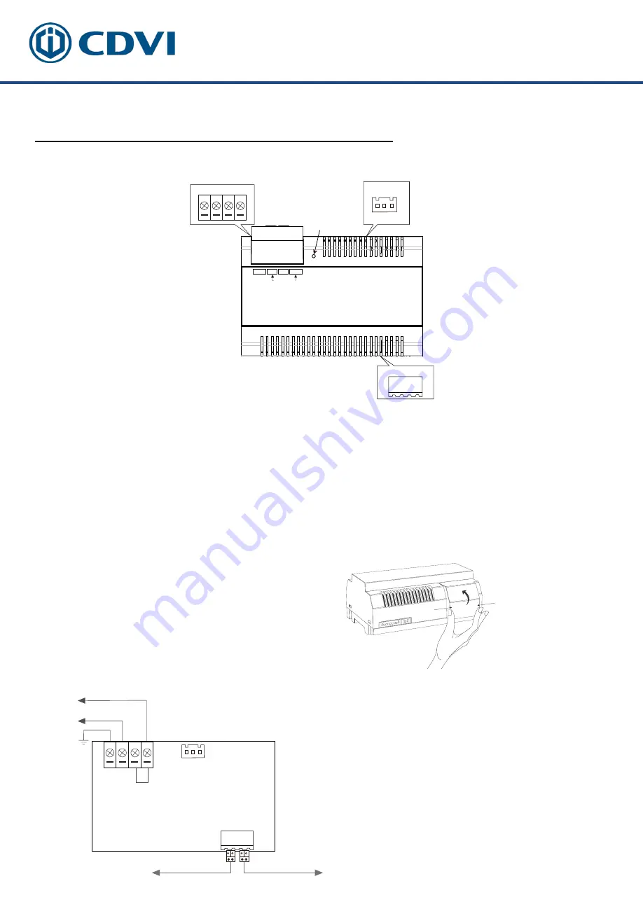
LED
CN
1 2 3
BUS(IM) BUS(DS)
N
L
PG
L
100~240 Vac
PG
N
L
L
CN
1 2 3
BUS(IM) BUS(DS)
AC Input
100~240Vac
N L
PG
L
*
Note:
1.
The AC cable is not included in the
package, it must comply
to the specific
requirements of country
where installed.
PG
:
Earth ground
terminal
.
N:
AC input
terminal
.
L:
AC input
terminal
.
LED:
P
ower indicator,
on when power connected
.
CN:
B
us control terminal.
BUS(IM):
I
ndoor monitor connection terminal.
BUS(DS):
D
oor station connection terminal.
4
Open the AC cover:
1.
Push the cover base towards
the cent
re with your fingers;
2.
Lift up and pull out the cover.
After connect
ing the AC cable, it is
advised to replace the cover.
2.
P
in
s
1&2 should be short-circuited
with a C3-3P li
nk
(included in the
package)
, if the unit
operates
as a
standard
power comb
iner. I
f
operating
as
an
auxiliary power comb
iner
,
the link should
be removed
.
Connect to monitor
Connect to door stat
i
on
3.2: Terminal Descriptions


