background image

-7-

SETUP INSTRUCTIONS

Functions Setting Up

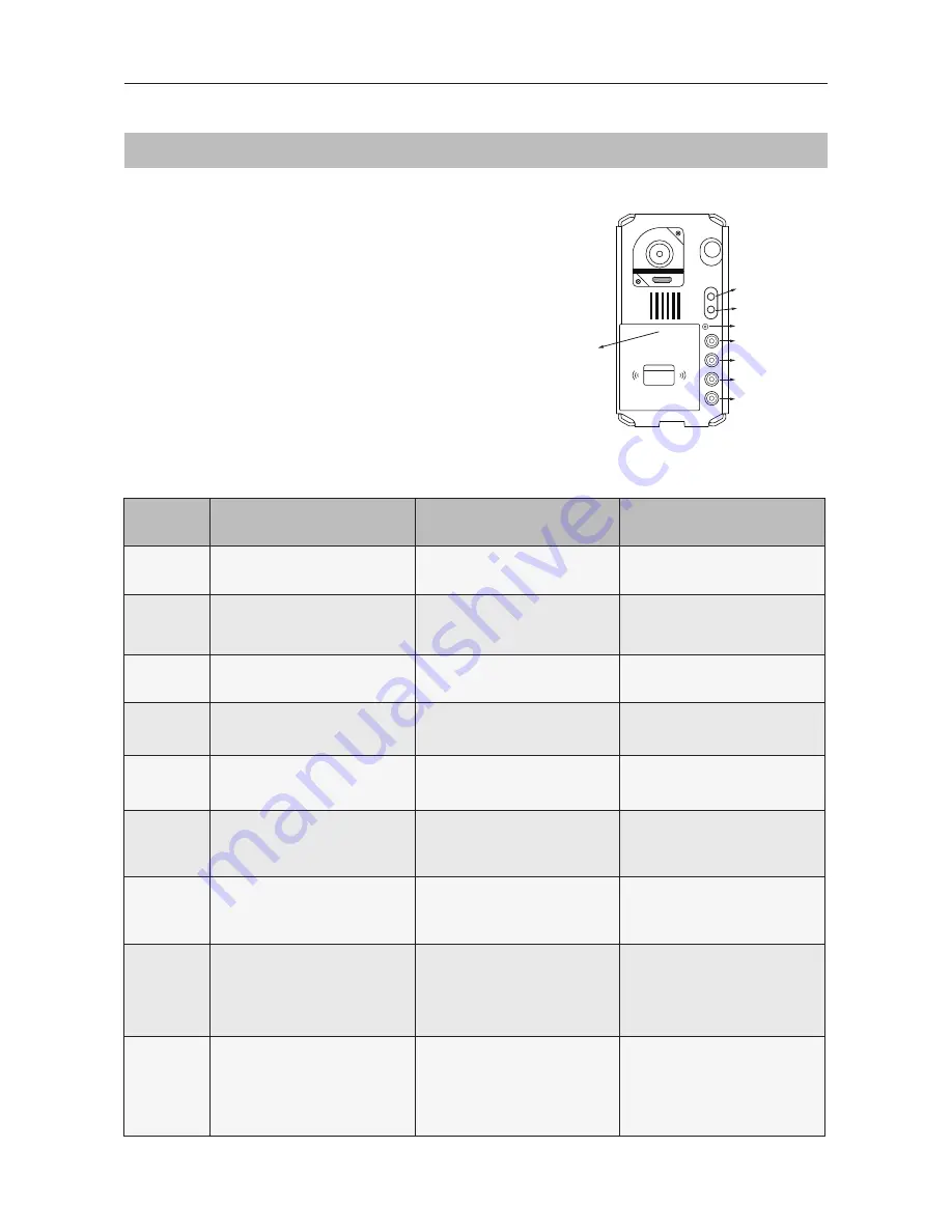
KEY_1

KEY_2

KEY_3

KEY_4

KEY_SET

LED_UNLOCK
LED_TALK

LED_NAME

RF CARD

Order

Setting items

Setting range

Default value

1

Setting door station address

0~3

0

2

Setting door station 

calling mode

Standard/Group calling mode

Standard calling mode

3

Setting camera resolution

High/Low

High

4

Setting the unlock mode

0:opened/1:closed

0:opened

5

Setting the unlock time

01 to 99 seconds

1 seconds

6

Setting the nameplate 

illumination mode

On/Off/Auto

On

7

Setting night view LED 

illumination mode

On/Off/Auto

Auto

8

Setting ring-back tone

Ringing one time

Ring continuously
No ring-back tone

Ringing one time

9

Setting image display mode

Alternate switching mode

Zoom mode

Full screen mode

Alternate switching mode

This section explains the settings of each 
function

. P

lease refer to the following table:

Each operation is indicated by the lighting 
of the

 LED

 indicator on the unit and by the 

sounding of the buzzer.

To perform the settings for the function 

required

,

 re

move the metal front panel

 to 

gain access to the 'Key Set' button

Please refer to the 

diagram (right)

.

Summary of Contents for CDV17-97A

Page 1: ...F CARD 2 WIRE SYSTEM Fisheye door station with proximity access control CDV97 V1 201609 CDV97 Series CDV97 4ID CDV97 1ID CDV97 2ID CDV17 97A Please read carefully to ensure safe and correct operation...

Page 2: ...de 8 Setting Camera Resolution 10 Setting Unlock Mode 10 Setting Unlock Time 11 Setting Nameplate Illumination Mode 11 Setting Night View LED Illumination Mode 12 Setting Ring back Tone 12 Setting Ima...

Page 3: ...8 7 6 5 12 11 12 13 13 2 2 Surface mounted Flush mounted 1 Microphone 2 UNLOCK indicator 3 CALL indicator 4 Call button 5 Nameplate 6 Front panel 7 Speaker 8 Night view LED 9 Camera lens 10 Rain Shiel...

Page 4: ...height is suggested at 145 160cm 3 Install the name plate 4 Attach the front panel to the main unit 5 Use the special screwdriver and the screws to fix the panel 1 Drill a hole in the wall to match th...

Page 5: ...ocks L1 L2 Connect to the bus line no polarity PL External lock power input connect to the power positive power S Lock power output S Lock power output connect to the power input of locks only when us...

Page 6: ...or will light up and the connected lock will release Please note that this function requires a monitor with fisheye function support The angle view is 1700 visitors within this angle of view can be se...

Page 7: ...plate illumination mode On Off Auto On 7 Setting night view LED illumination mode On Off Auto Auto 8 Setting ring back tone Ringing one time Ring continuously No ring back tone Ringing one time 9 Sett...

Page 8: ...Beep Beep Beep Beep SETUP INSTRUCTIONS A total of 4 addresses can be configured They can be modified either before or after installation 0 is default to change the setting please use the following ste...

Page 9: ...efault Call button A Calls all the monitors in the group address 00 15 One monitor must be set to 00 Call buttons B C D Calls all the monitors in the group address 16 31 One monitor must be set to 16...

Page 10: ...1 button again to set the unlock mode to Normally closed Press KEY_1 SETUP INSTRUCTIONS The resolution of the camera can be changed between high and low quality at the door station If no operation is...

Page 11: ...3 By default the unlock time is 1s this can be changed between 1s 99s Follow the steps below If no operation is carried out within 10 s the setting mode will exit automatically To exit the setting mod...

Page 12: ...uto Auto is default to change the setting please use the following steps While in the setting mode the calling code can be changed mode by pressing KEY 4 cyclically The LED_NAME indicator will continu...

Page 13: ...d the image will switch between Full screen and Zoom image at a time interval of 5 seconds Full screen mode when the monitor is called the image will be displayed in Full screen Zoom mode when the mon...

Page 14: ...ly To exit the setting mode manually press the KEY_SET button four times While in the setting mode the calling code can be changed mode by pressing KEY 3 cyclically The LED_NAME indicator will continu...

Page 15: ...w the second card to ID card window set the card of MASTER CARD DELETE UNLOCK Indicator OFF TALK Indicator OFF Buzzer Beep Beep UNLOCK Indicator Blink one time TALK Indicator OFF Buzzer Beep Press KEY...

Page 16: ...Show the master card of MASTER CARD DELETE to ID card window in standby UNLOCK Indicator ON TALK Indicator ON Buzzer Beep Beep UNLOCK Indicator Blink for some time TALK Indicator Blink for some time B...

Page 17: ...jumper 1 2 3 L1 L2 PL S S LOCK POWER SUPPLY WIRING 1 Electronic lock of Power on to unlock fail Secure type should be used 4 The door lock control is not timed from Exit Button EB 2 The door lock is...

Page 18: ...ID 0 1st door station ID 1 2nd door station ID 2 3rd door station ID 3 4th door station L1 L2 PL S S L1 L2 PL S S L1 L2 PL S S L1 L2 PL S S To monitors RF CARD RF CARD RF CARD RF CARD The door statio...

Page 19: ...atible with other monitors within the 2Easy range Please set door station into group calling mode if there is more than 4 monitors in villa house or apartment Refer to Page 9 A distributor is unnecess...

Page 20: ...lifier module RLC staircase light controller module DBC4A1 2 4 inputs branch distributor Star Topology Wiring With DBC4A1 in Standard Mode The door station is also compatible with other monitors from...

Page 21: ...52 D mm flush mounted The unit is weather resistant However do not spray high pressure water on access control keypad directly excessive moisture will damage the unit You must use the right adaptor su...

Page 22: ...asic IN OUT Wiring Mode The maximum distance of the wiring is limited within the 2Easy system Using different cables may also affect the maximum distance which the system can reach Cable Usage A B 2 I...

Page 23: ...23 B A C 2 2 DBC4A1 RF CARD PC6A Cable and distance unit m APPENDIX Star Topology Wiring Mode With DBC4A1 Cable Usage A B C Belden 9740 UTP 2x0 75mm 2 60 60 30 Belden 8471 UTP 2x1mm 2 80 80 40...

Page 24: ...CDV ENG 97 V1 The design and specifications can be changed without notice to the user Right to interpret and copyright of this manual are preserved...

Reviews: