

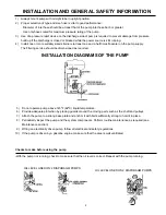


- Check to make sure that the inlet, discharge and by-pass hoses have the correct diameter, i.e. never smaller than
the union on the pump. The hoses should not be crimped and the hose clamps should be sized for hose diameter.
- Prevent any hose restrictions and be sure connections are tight to prevent air entering, since these conditions will
compromise pump performance.
- If pumping from a tank, check to make sure that the control unit by-pass line is not too close to the inlet line. Make
sure that it does not create turbulence inside the tank.
- Check air pressure in the pulsation damper. It should be kept within specs given in the Chart on the Service Manual.
- The pressure regulator lever should be turned downward. Whenever the by-pass jet is used, the pressure
adjustment lever must be turned in the down position so that the pressure is zero.
- Check to make sure the strainer is clean. Be sure the cartridge is reinstalled and tightened to assure no suction
leak.
- Check for leaks.
Suction Head
Do not use suction head for filling the tank. Avoid suction head higher than 10 feet.
In this case, some troubles may occur in the pump parts.
Operation Instructions
- Start pump and let run for approximately one minute at zero pressure to facilitate priming. Once primed, the pump
is ready and can be set to run at the desired pressure by moving the lever downwards and turning the adjustment
knob clockwise.
- Operating pump above recommended rpm will not improve performance but rather may damage the pump.
Operation at rpm higher than specifications voids all warranties.
- Working pressure should be selected with the discharge line closed and all liquid in by-pass.
- While the pump is running, check the oil level in sight glass. This
acts as an emergency indicator to signal
malfunction,
e.g. if the diaphragm breaks, the oil will become white. Stop the pump immediately.
- Do not rotate the shaft for long periods without liquid in the cylinders or in the suction line.
- If the pump is driven by a PTO shaft and sprayer makes a sharp turn, disconnect the tractor PTO to prevent damage
to the shaft supports and to the crankcase.
- If oil volume increases due to high operating temperature and the oil reaches the level of the plug, stop the pump to
prevent damage from internal overpressure.
After Use
After use, in order to prevent damage, flush pump and let operate for a few minutes at working pressure with
a solution that will neutralize the liquid last pumped (refer to that manufacturer’s instructions). Afterward empty the
pump, so that the pressure drops to zero (“0”), and then let the pump run without liquids for two minutes.
To protect pump from freezing,
flush pump per instructions above (after use) and then flush with straight
RV-antifreeze. Empty the pump per the instructions above.
Ordinary Maintenance
Change oil every 500 hours as follows:
- Remove cap from oil sight tube and drain plug.
- Turn pump upside down and rotate the shaft by hand until oil stops flowing out.
- It is recommended to make an inside washing with gasoline or diesel oil.
- Put the drain plug back and pour oil into sight tube while turning the pump shaft. Be sure oil is at the indicated level
and care not to exceed it.
- Start the pump at pressure “0” for a few minutes to allow the correct lubrication of inside parts, then check oil level.
3


