32
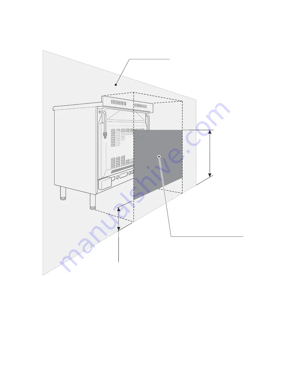
IMPORTANT PRESCRIPTIONS FOR GAS CONNECTION
700 mm
Rear wall
Suggested area for gas mains connection
200 mm
Fig. 36
Page 1: ...Gas cookers RC 9300 Users Operating Instructions Installation instructions GB Before operating this cooker please read these instructions carefully...
Page 2: ...iance is used within a non domes tic environment i e a semi commercial commercial or communal environment Dear Customer Thank you for choosing one of our appliances carefully designed and built by our...
Page 3: ...w to use the gas grill 12 Oven light 13 Rotisserie 14 Do s and do not s 15 Important notes 16 Care and maintenance 17 For the installer Location 24 Fitting the adjustable feet 25 Stability bracket 27...
Page 4: ...n the maximum benefits from your appliance Fig 1 Assembling the backguard Remove the two spacers A and the screw B from the rear of the cook top Assemble the backguard as shown in figure 1 and fix it...
Page 5: ...5 Features and technical data Fig 2 2 4 3 1 1 2 Gas burners 1 Auxiliary burner A 1 00 kW 2 Semi rapid burner SR 1 75 kW 3 Rapid burner R 3 00 kW 4 Triple ring burner TR 3 50 kW...
Page 6: ...nob 6 Rear central burner control knob 7 Rear right burner control knob 8 Front right burner control knob 9 Oven light rotisserie control knob 8 9 Minute counter Minute counter The minute counter is a...
Page 7: ...of the burners is difficult due to peculiar conditions of the gas features or supply it is advised to repeat the ignition with the knob on minimum position Hob burners Each hob burner is controlled by...
Page 8: ...ikely to tip Pans which are positioned centrally on burners are more stable than those which are offset It is far safer to position the pan handles in such a way that they cannot be accidentally knock...
Page 9: ...onto the pan support To use the WOK you need to place the proper stand in order to avoid any faulty operation of the triple ring burner Fig 7 8 IMPORTANT The special grille for wok pans fig 8 MUST BE...
Page 10: ...5 seconds If the burner has still not ignited wait for about 1 minute prior to repeating the ignition 4 Wait about 10 15 seconds after the burner lighting before releasing the knob time of priming of...
Page 11: ...Dundee 195 C Warm oven Biscuits rich plain cakes i e Madeira Low temp roasting 210 210 C Moderate Plain cakes Victoria oven sandwich raised meat pies 225 C Fairly hot Small cakes savoury flans oven fi...
Page 12: ...still not ignited wait for about 1 minute prior to repeating the ignition 4 Wait about 10 15 seconds after the burner lighting before releasing the knob time of priming of the valve 5 Half close the...
Page 13: ...14 The cooker is equipped with a light that illuminates the oven to enable visually controlling the food that is cooking This light is controlled by a switch knob fig 14 Fig 13 IMPORTANT WARNING For...
Page 14: ...tisserie Insert the tray into the lowest rack holders of the oven and insert the rod support into the intermediate rack holders Put the meat to be cooked onto the rod being careful to secure it in the...
Page 15: ...ker when in use Do not allow fat or oils to build up in the oven trays or oven base Do not place cooking utensils or plates directly onto the oven base Do not grill food containing fat without using t...
Page 16: ...omestic foodstuffs Under no circumstances should any external covers be removed for servicing or main tenance except by suitably qualified personnel Attention The appliance gets very hot mainly around...
Page 17: ...is recommended when han dling or cleaning of this appliance WARNING When correctly installed your product meets all safety requirements laid down for this type of product category However special car...
Page 18: ...parts must be cleaned with a sponge and soapy water only or other non abrasive products Dry preferably with a microfibre or soft cloth Stainless steel aluminium painted parts and silk screen printed s...
Page 19: ...rrectly positioned see fig 17 failure to do so can cause serious problems Check that the electrode S fig 17 is always clean to ensure trouble free sparking Note The electrode S must be very carefully...
Page 20: ...he inner glass door panel The inner glass door panel can easily be removed for cleaning by unscrewing the four screws fig 20 When re assembly ensure that the inner glass is correctly positioned and do...
Page 21: ...ty for damage caused by chemical or abrasive cleaning Let the oven cool down and pay spe cial attention no to touch the hot heat ing elements inside the oven cavity Assembling and dismantling of the s...
Page 22: ...Open the door completely The swivel retainers of the rh and lh hinges fig 25a are hooked onto the metal bar above them fig 25b Lift the oven door slightly The noch on the bottom of the hinge will dis...
Page 23: ...talled in a bed sitting room of less than 20 m3 The appliance is designed and approved for domestic use only and should not be installed in a commercial semi commercial or communal environment Your pr...
Page 24: ...acent to the cooker must be made of material resistant to heat The veneered synthetic material and the glue used must be resistant to a temperature of 90 C in order to avoid ungluing or deformations C...
Page 25: ...ear of the cooker an a piece of the polystyrene packaging exposing the base for the fitting of the feet Fit the 4 legs by screwing them tight into the support base as shown in picture 28 WARNING When...
Page 26: ...n raising to the upright position fig 30 WARNING When moving cooker to its final posi tion DO NOT DRAG fig 31 Lift feet clear of floor fig 29 Levelling the cooker The cooker may be levelled by screw i...
Page 27: ...shown in fig 33 can be purchased from most plumbers merchants and do it yourself D I Y shops Wall fixing Floor fixing Brackets Existing slot in rear of cooker Dotted line showing the position of cooke...
Page 28: ...side air in which case no permanent ventilation is required For rooms with a volume greater than 10 m3 no permanent ventilation is required NB Regardless of room size all rooms containing the applianc...
Page 29: ...y a competent person in accordance with the current editions of the following Standards Regulations or those regulations appropriate to the geographical region in which they are to be installed Gas Sa...
Page 30: ...ity should install the appliance He should observe the Regulations and Codes of Practice governing such installation of gas appliances Note It is recommended that the gas connection to the appliance i...
Page 31: ...o be connected in such away that it does not touch the floor To screw the connecting tube operate with two spanners fig 35 The unused end inlet pipe must be closed with the plug interposing the gasket...
Page 32: ...32 IMPORTANT PRESCRIPTIONS FOR GAS CONNECTION 700 mm Rear wall Suggested area for gas mains connection 200 mm Fig 36...
Page 33: ...in hundredths of a millimetre are marked on the body of each injector To replace the injectors proceed as follows Remove the grids and extract the burner bodies Using a wrench substitute the nozzle i...
Page 34: ...t even with a quick turn from the maximum position to that of mini mum The flame adjustment is done in the following way Turn on the burner Turn the tap to the MINIMUM position Take off the knob With...
Page 35: ...30 G 30 28 30 mbar G 20 BURNERS G 31 37 mbar 20 mbar Auxiliary A 1 00 0 30 27 50 72 X Semi rapid SR 1 75 0 45 32 65 97 Z Rapid R 3 00 0 75 42 85 115 Y Triple ring TR 3 50 1 50 65 95 135 T Oven 6 20 1...
Page 36: ...injectors operating as follows remove the oven bottom unscrew and remove the burner fixing screw A fig 40 slacken screw B fig 40 slip the burner itself from the oven Fig 41 Take care not to damage th...
Page 37: ...crew C fig 42 Slacken screw D fig 42 Move and gently suspend the burner as shown in figure 43 Take care not to dam age the wire to the ignition electrode and the safety valve probe Remove the injector...
Page 38: ...ow accord ing to the Table for the choice of the injec tors Light the burner and check the flames Primary air of the grill burner With a screwdriver untighten the screw fig 45 and turn the air ring to...
Page 39: ...ig 46 fit the knob and let the oven heat for 10 minutes then take the knob to position 150 allowing the thermostat to work under by pass after further removal of the knob stop slowly the screw by pass...
Page 40: ...OVED FOR ANY OTHER REASON THEN THE FUSE SHOULD BE REMOVED AND THE CUT OFF PLUG DISPOSED OF SAFELY TO PREVENT THE HAZARD OF ELECTRIC SHOCK THERE IS A DANGER OF ELECTRICAL SHOCK IF THE CUT OFF PLUG IS I...
Page 41: ...the appliance see the section Feeder cable section Connect the wires to the terminal block B as shown in the diagram in figure 49 or connect the phase wires to the terminal block B and the earth wire...
Page 42: ...owing information available when booking a service call 1 Model type make and model see the product data plate 2 Evidence of installation purchase date 3 Retailer where appliance was purchased 4 Clear...
Page 43: ...date must be produced before a service call will be booked The appliance must be used for domestic purposes only Appliances used for com mercial or professional purposes are not covered by the guarant...
Page 44: ...considering the characteristics of the models described here at any time and without notice to make eventual necessary modifications for their construction or for commercial needs RC 9300 cookers The...