background image

Supplied with the appliance is a plastic

(self adhesive) anticondensation strip,

this should be fixed to the underside of

your worktop along the front edge. The

adjustable feet of the appliance allow it

to be raised up to 870mm, if the space

between the floor and the underside of

the work surface is greater than 870mm,

Stage 1

To prevent damage to the floor covering, the appliance must be

installed using the plastic skids provided.

Stage 2

Connect the water, drain and electrical supplies (220 - 240V,

50Hz). We recommend that the appliance is connected to a cold

water supply.

Measure the width of the decor door.Align the template on the

rear of the door with the top of the door level with the top of the

template, and the left hand edge of the door in line with the mea-

sured door width. Mark the four fixing poisitions. Repeat on the

right hand side. Remove the template, and drill pilot holes in the

door in all eight positions using a suitable drill (take care not to

drill through the door). Attach the upper plastic studs and lower

fixing brackets to the decor door as shown below.

Stage 3

Position the decor door onto the front of

the dishwasher by locating the brackets

into the two plastic studs mounted ei-

ther side on the top of the door. Lift the

decor door until the lower brackets lo-

cate into the slots in the appliance door.

Stage 4

then the  appliance should be positioned on suitable wooden

spacers which should always be fixed to the floor. Always use a

spirit level to make sure that the appliance is level left to right

and front to back.(If the appliance is installed on a carpet, en-

sure there is clearance beneath the appliance). The four adjust-

able feet should be adjusted to the correct height; the rear feet

are adjustable via studs at the front of the appliance (fig 1a).

fig 1a

Align the top of the decor door with

adjacent cabinets. Gently open door

whilst supporting the decor door.

Once in the lowered position, secure

the decor door using the fixing

screws provided as shown in the

diagram. Cover the screw heads

using the plastic caps provided.

Stage 5

The dishwasher should now be screwed to the underside of the

worktop, via the two fixing holes in the top trim.

For non-wooden worktops (e.g. marble) two brackets are pro-

vided to allow the appliance to be secured to the sides of the

adjacent cabinets. The should be secured to the appliance us-

ing the two screws at the top of the chassis (see fig 1b), ad-

justed to the correct width and then screwed to the adjacent

sides panels using suitable screws.

Stage 6

The door balance can be adusted via two screws accessed

through two holes in the top of the front frame. Adjust these until

the door just remains open under its own weight and is level

when open.

Stage 7

Cut clearance in the plinth to allow the door to open fully and

seal edges with a suitable varnish to prevent water ingress.

Stage 8

Installation cont..

.11.

GB

Summary of Contents for CW495

Page 1: ...Integrated Dishwasher CW495 Users Operating Instructions Before operating this appliance please read these instructions carefully ...

Page 2: ...rised person The guarantee does not cover damage caused by transit or by misuse accident abuse or neglect The guarantee does not cover routine maintenance Use of parts not supplied or recommended by CDA will invalidate the warranty Rubber seals filters removable glass parts control knobs and buttons fuses and light bulbs which need replacing periodically are not covered by the guarantee Second han...

Page 3: ...r If the appliance malfunctions turn off water supply to the appli ance and disconnect the plug from the wall socket Then con sult the section entitled Troubleshooting If you cannot re solve the problem contact a service centre Only specialised personnel are authorised to make repairs Appliances which are no longer being used must be made inop erable by cutting the power supply cord and removing t...

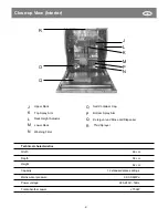
Page 4: ...ck O P Q R Washing Filter Detergent and Rinse Aid Dispenser Third Sprayer Salt Container Cap Bottom Spray Arm Technical characteristics 60 cm 58 cm 82 cm 12 standard place settings 0 03 0 6MPa 220 240V 50Hz 2150W Width Depth Height Capacity Mains water pressure Power voltage Total absorber power M O Q R GB ...

Page 5: ...iner must be filled when the low salt indicator light located on the control panel comes on To prevent the formation of rust load the salt just be fore beginning a wash cycle Adjusting Salt Consumption The dishwasher is designed to allow for adjusting the amount of salt consumed based on the hardness of the water used This is intended to optimize and customize the level of salt consump tion so tha...

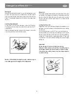
Page 6: ... The dispenser is located on the inside panel of the door and should be filled after every 80 wash cycles or when the low rinse aid indicator light comes on for those models with this feature Loading the Rinse Aid Regardless of the type of detergent dispenser installed on your appliance you must proceed as indicated below when loading the rinse aid To open the dispenser turn the C cap in an anti c...

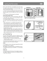
Page 7: ...used when the silverware load is light This also makes space for additional pots and pans and it can also be placed in the upper rack Silverware should be placed in the silverware basket with the handles at the bottom if the rack has side baskets the spoons should be located individually into the appropriate slots Espe cially long utensils should be placed in the horizontal position at the front o...

Page 8: ...efully in order to avoid being sprayed by hot water When the door is closed again the cycle will automatically restart at the point where it left off At the end of the wash cycle The end of the cycle will be indicated by a double acoustical signal and the blinking of the G indicator light And the number on the display I will turn 0 Open the door turn off the appli ance using the power botton and t...

Page 9: ...le to be used to on not very dirty dishes right after they are used No dry ing cycle Pre wash of dishes pots and pans while waiting for the load to be completed after the subsequent meal Pre wash with hot water Extended wash at 70 K Rinses with cold water Rinse with hot waterK Drying pre wash with cold water Extended wash at 55 Rinse with cold water Rinse with hot water Drying Wash at 60 Rinse wit...

Page 10: ...be moved try to keep it in a vertical position If absolutely necessary it can be positioned on its back Moving the Appliance One of the factors that cause odors to form in the dishwasher is food that remains trapped in the seals Periodic cleaning with a damp sponge will prevent this from occurring Seals Cleaning and Special Maintenance Filter Assembly For best performance and results the filter as...

Page 11: ...n the Dishes Have you checked whether the lid to the salt container is closed properly the rinse aid dosage is correct Error Messages The dishwasher is equipped with a safety system that is able to detect operating problems and malfunctions These malfunctions are signalled by the rapid blinking of one of the M program LEDs Only in the case where the indicator light for the soak cycle see table for...

Page 12: ...ected to the house s hot water line centralised system heating system as long as it does not exceed a temperature of 60 In this case the wash cycle time will be shortened by about 15 minutes and the wash efficiency slightly reduced The connection must be made to the hot water line following the same procedures as those for the connection to the cold water line fig 2 Drain Hose Connection Insert th...

Page 13: ...hen the appliance should be positioned on suitable wooden spacers which should always be fixed to the floor Always use a spirit level to make sure that the appliance is level left to right and front to back If the appliance is installed on a carpet en sure there is clearance beneath the appliance The four adjust able feet should be adjusted to the correct height the rear feet are adjustable via st...

Page 14: ...Installation Diagram 12 GB ...

Page 15: ... booking a service call 1 Model type make and model see the front of this manual 2 Evidence of installation purchase date 3 Retailer where the appliance was purchased 4 Clear and concise details of the fault 5 Full address including postcode and any contact phone numbers Contact telephone numbers CDA Customer Care Department Harby Road Langar Nottingham NG13 9HY Telephone 01949 862000 Email servic...

Reviews: