V4 or RS485
9
Tx
-
Transmitter
1
. Connect the 3 video input signals into ‘Video In’ ports 1 to 3 of the transmitter (figure 1, 1-3).
2
. Connect an audio input device such as a microphone into ‘Video In’ port 4 of the transmitter (figure 1, 4).
3.
Check the ‘V4 or RS485’ switch (figure 11a) is set to V4.
4
. Connect the RG59 co-ax cable into the ‘Video Out’ port (figure 1, 6) the maximum length is 200 metres.
Rx
-
Receiver
1.
Connect the RG59 co-ax cable from the transmitter to the ‘Video In’ port (figure 2, 5) of the receiver.
2.
Connect the 3 video cables from your DVR to the ‘Video Out’ marked 1 to 3 of the RX unit (figure 2, 1-3).
3.
Connect an audio output device such as the VoiceOff into ‘Video Out’ port 4 (figure 2, 4).
4.
Check that the ‘V4 or RS485’ Switch (figure 11a) is set to V4.
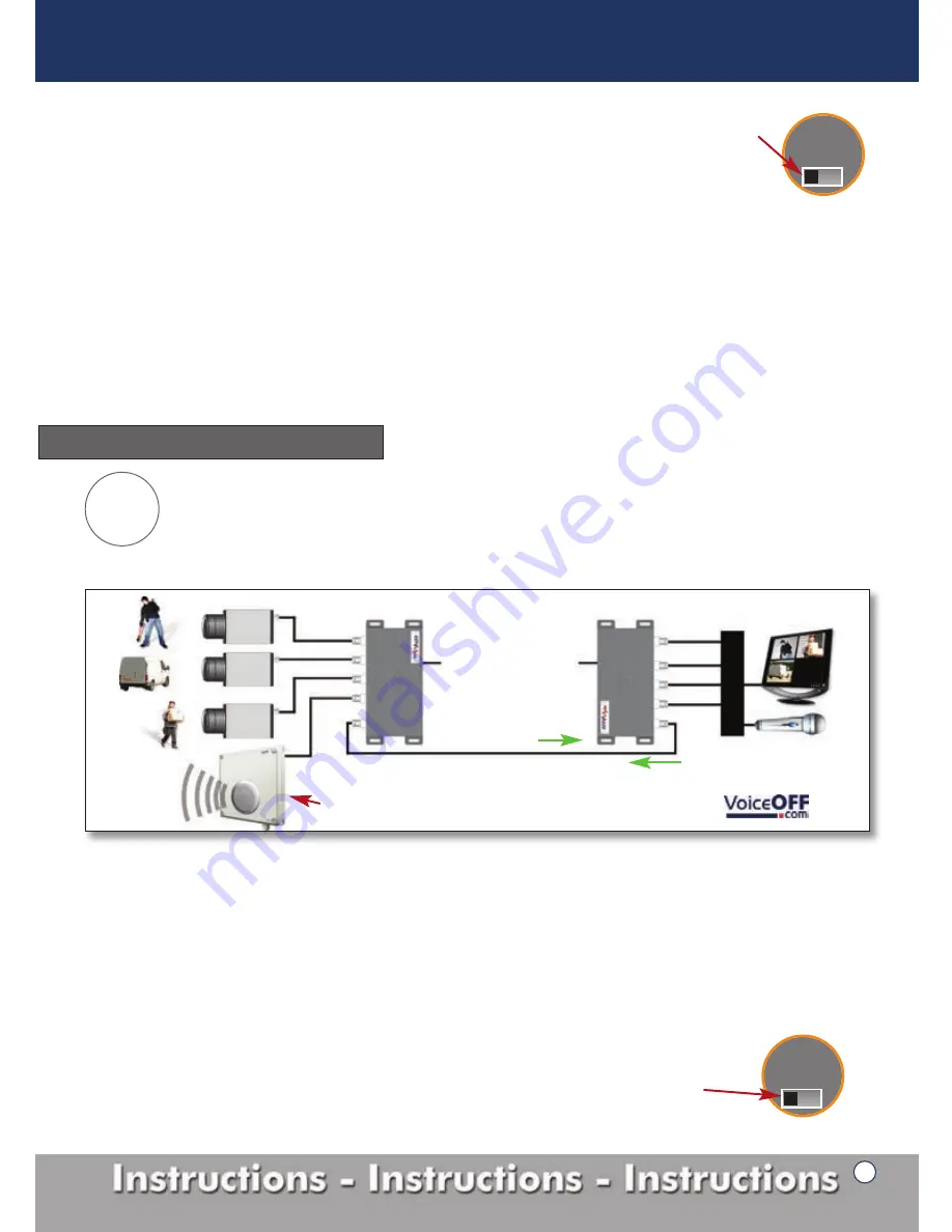
3 Video signals in one direction, 1 audio signal in the opposite direction.
The Mule4 is capable of transmitting audio in the reverse direction to 3 video camera signals. This mode works especially
well in an existing installation where 1 of the cameras could be converted into a tannoy system using the VoiceOff. No
additional cabling would be required to complete this setup. Figure 12 shows a diagram of how mode 5 is configured.
Operation Mode Setup
Mode
5
1x RG59 co-ax cable
D
V
R
Mule 4 -
Tx
Mule 4 -
Rx
12V DC
12V DC
V1
V2
V3
V1
V2
V3
Audio
Audio
V1, V2 & V3
in this direction
New
VoiceOFF
- Alarm activated voice/sound warning unit, see >>>
Audio
in this direction
Figure 12
Tx
-
Transmitter
1
. Connect the 3 video input signals in to ‘Video In’ ports 1 to 3 of the transmitter (figure 1, 1-3).
2
. Connect an audio output device such as the VoiceOff into ‘Video In’ port 4 of the transmitter (figure 1, 4).
3.
Check the ‘V4 or RS485’ switch (figure 12a) is set to V4.
4
. Connect the RG59 co-ax cable into the ‘Video Out’ port (figure 1, 6) the maximum length is 200 metres.
Rx
-
Receiver
1.
Connect the RG59 co-ax cable from the transmitter to the ‘Video In’ port (figure 2, 5) of the receiver.
2.
Connect the 3 video cables from your DVR to the ‘Video Out’ marked 1 to 3 of the RX unit (figure 2, 1-3).
3.
Connect an audio input device such as a microphone into ‘Video Out’ port 4 (figure 2, 4).
4.
Check that the ‘V4 or RS485’ Switch (figure 12a) is set to V4.
Mode 4 setup continued...
Switch in ‘V4’ position
on both units.
Switch in ‘V4’ position
on both units.
Figure 11a
Figure 12a
CCTV Mule Instructions
V4 or RS485


