
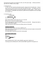
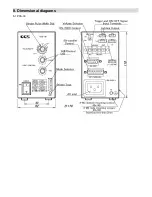
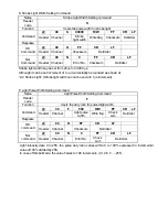

2-4 Strobe Light
Refer to other sections for the settings at # 2, # 3, # 4, and 6.
Dip switch # 5 is not used in strobe light.
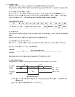
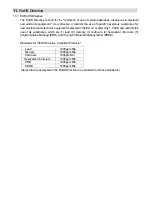
Light pulse width: 20, 40, 60, 80,100,140,180, 260, 400, 500, and 1,000
µ
s or 3, 5, 8, 10, and 33 ms
(±10 ms).
Overdrive is activated with 3 to 4 times the light output for light pulse width of 1,000
µ
s or less.
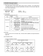
Strobe Lighting Control
When the light pulse width more than 3 ms, output voltage becomes for normal continuous light and
overdrive becomes disabled. Strobe light can be adjusted by 128 levels combining the coarse and
fine rotary dials.
Light intensity date: (Coarse x 16 + Fine) x 100/255 [%]
(Note1, Note2)
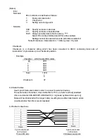
Note: however, that the fine rotary dial controls strobe delay time rather than light control when DIP
switch # 6 is ON. (Refer to 2-5)
Notes
1: This is a theoretical value. It varies by loads and extension cables, especially around 0% as well
as 100% setting.
2: Strobe light resolution becomes half to 128 levels. (128 levels: 0,1,3,5,7,…,255)
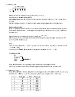
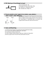
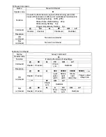
Trigger Input Wiring
NC
TRIGGER
ON/OFF
GND
When DIP switch # 4 is OFF and trigger input signal is ON, strobe light turns ON.
Conversely, when DIP switch # 4 is ON and trigger input signal OFF, strobe light turns ON.
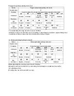
2-5 Light Delay Time
When DIP switch # 6 is ON, the delay time from the trigger input until the light turns ON, may be set by
fine rotary dial. In this case, only the coarse rotary dial is used for light control (error ±10
µ
s).
Trigger input
Fine
Delay [
µ
s]
Fine
Delay [
µ
s]
0 10 8
300
1 30 9
500
2 60 A
750
3 80 B
1000
4 100 C
2000
5 150 D
4000
6 200 E
8000
7 250 F
10000