
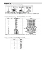
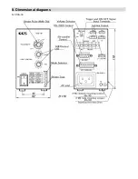
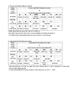

4. Connectors
4-1 Output connector: SM connector (mfd. by JST)
Pin No.
12 V output
24 V output
Output with fan
(Note)
1
OUT+(+12V)
OUT+(+24V)
OUT+(+24V)
2 OUT- NC
OUT+(+12V)
3 OUT-
OUT-
4
Fan
GND
Connector SMP-02V-BC SMP-03V-BC SMP-04V-BC
Note) With fan: L1/L2 (FAN) output connector for lighting with a fan
Output with fan is not available when strobe (ON) is selected with mode selector DIP switch # 1.
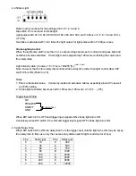
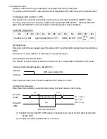
4-2 External interface connector: (15-pin D-sub plug with M2.6mm Screws)
Use a shielded cable no longer than 3m for the control line.
Pin No. Color of the Optional Cable
(Note)
Signal
1
Black
Light intensity date B1[LSB]
2
White
Light intensity date B2
3
Red
Light intensity date B3
4
Green
Light intensity date B4
5
Yellow
Light intensity date B5
6
Brown
Light intensity date B6
7
Blue
Light intensity date B7
8
Purple
Light intensity date [MSB]
9
Gray
External control (INIT/EXT) B9
10 Pink
Light intensity data write (/WR) B10
11
White/Black
ON/OFF control (ON/OFF)
12
Red/Black
Trigger input (/TRIG) B12
13
Green/Black
Trigger delay output (TDLY) B13
14
Yellow/Black
Pulse output (FLSH) B14
15 Brown/Black
Signal
GND
Note) Optional cable for external control: EXCB2-B3 (3m long cable with one end cut.)
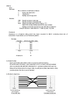
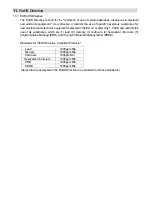
4-3 RS-232C Connector 9-pin D-sub plug with inch screws
Use a shielded crossover cable no longer than 3 m for the control line.
Pin No.
Signal
1 NC
2 RXD
3 TXD
4 DTR
5 GND
6 DSR
7 RTS
8 CTS
9 NC