Fastrax
TM
1.855.244.3128
Fax: 1.303.979.7350
[email protected]
www.fastraxind.com
32
H. SYSTEM WIRING DIAGRAMS
H.1 STAND ALONE CONTROL PANEL WIRING DIAGRAM (1) NO. 9, 10, OR 11 SWITCH & SPRING FROG
HEATING SYSTEM
Page 1: ...Installation Operations Manual G Series Control Panel Package...
Page 2: ...Mast 16 Junction Box Installation Junction Box Placement 17 Direct Burial Cable Conduit Trenching 17 Direct Burial Cable Conduit Junction Box Installation 18 SwitchBlade Heater Installation SwitchBlad...
Page 3: ...40 Extension Control Panel Wiring Diagram 2 No 9 10 Or 11 Switch Spring Frog Heating System 41 Extension Control Panel Wiring Diagram 1 No 14 15 Or 16 Switch Spring Frog Heating System 42 Extension C...
Page 4: ...Power Operated Turnout with 2 Power Operated Movable Point Frog Hollow Metal Ties Master Control with Extension Panels Quantity Required Fastrax Part No Description 1 FCM4 Fastrax Master Control Panel...
Page 5: ...ster Control Panel Maximum 4 Slaves FCM4 NONE Fastrax Master Control Panel Control maximum of 4 Extension panels of any size Minimum 10 Amp 120 Volt 1 phase required Enclosure size 36 H X 30 W X10 D P...
Page 6: ...d panel installation are complete 2 Using a socket wrench remove lag bolts from the crate 3 Open the panel and check that the nameplate information matches the Bill of Material list 2 0 Control Panel...
Page 7: ...stem Checkout sheet located at the back of the manual 4 0 Junction Box Assembly Ensure that each junction box has a corresponding support pedestal 5 0 Installation Accessories Unpack the installation...
Page 8: ...d com www fastraxind com 8 B 2 SINGLE STAND ALONE SWITCH WITH FROG No 9 No 11 Switch and Frog No 14 No 16 Switch and Frog No 20 24 Switch and Frog TYPICAL OVERALL LAYOUT FOR SINGLE SWITCH WITH FROG NO...
Page 9: ...nologies Inc 9 B 3 CROSSOVER NO 20 24 SWITCHES WITH FROGS Single Crossover No 20 or No 24 Switches with Frogs FA S T R A X R R R Double Crossover No 20 or No 24 Switches with Frogs FA S T R A X R R R...
Page 10: ...d for general positioning of equipment only Review your company standards for exact equipment layout TYPICAL SYSTEM LAYOUT EQUIPMENT DETAIL NO 9 10 OR 11 STANDARD SWITCH SIZE ALL TIE STYLES Fastrax FJ...
Page 11: ...equipment only Review your company standards for exact equipment layout TYPICAL SYSTEM LAYOUT EQUIPMENT DETAIL NO 14 15 or 16 STANDARD SWITCH SIZE ALL TIE STYLES Fastrax FJA or FJAM Junction Box Fast...
Page 12: ...general positioning of equipment only Review your company standards for exact equipment layout TYPICAL SYSTEM LAYOUT EQUIPMENT DETAIL NO 20 24 STANDARD SWITCH SIZE ALL TIE STYLES Fastrax FJA or FJAM...
Page 13: ...of Frog To Fastrax Control Panel Heel of Frog Fastrax Junction Box Fastrax SwitchBlade Heater Inserted in milled slot or clamped to D Bar of the Spring Rail Frog Movable Point Frog Heating Layout Typi...
Page 14: ...op of the unistrut channels at the 11 mark Figure C 1 2 Control panel positioning 3 Slide one of the 3 8 channel nuts above and below the four control panel mounting holes Use one 3 8 x 1 1 2 bolt and...
Page 15: ...ing conduit underground cables 2 0 If PVC Conduit is provided 1 Two 4 conduits are provided One conduit is for the direct burial conductors coming from the switch and frog junction boxes The other con...
Page 16: ...n the back of the panel support channel 3 Locate mark and cut the preferred location for the 1 2 fitting to enter the bottom of the control panel 4 Using the 1 2 opening in the panel bottom install th...
Page 17: ...unction Box Note Follow Railroad guidelines and specifications for trenching to prevent damage to existing buried lines Always locate and mark existing cables before digging 3 For the placement of the...
Page 18: ...height of the junction box Figure D 1 7 Direct Burial Cable Junction Box Note For direct burial cables use the glands provided in the accessory kit to properly terminate the cable for entry into the j...
Page 19: ...r heater to move freely 4 Mark the rail where clamps are to be installed Heaters should be clamped about every 2 ft A common rule of thumb is to clamp each heater in every crib space It is acceptable...
Page 20: ...nt it from seating on the rail 3 The end of the clamp body will wrap around the gage side of the rail when seated properly 4 Tighten each clamp by turning the swivel screw with an Allen wrench until t...
Page 21: ...ay the rear heater in place while feeding the dead end in from the heel block location Bring the dead end to about 2 from the dead end of the front heater 2 If necessary adjust both heaters to allow f...
Page 22: ...fish tape if necessary 6 The heaters generally will have a piece of cold shrink strain relief rubber over the area where the wire enters the heater Slip the orange conduit as far as it will go over t...
Page 23: ...on to confirm that the installed track switch appears as shown in Figure 3 Note Proper heater clearance must exist above the reinforcement bolts to allow for an unobstructed path for heater element to...
Page 24: ...s have a rectangular channel manufactured into the base of the frog casting The channel is designed to extend from the frog heel to the toe and is open on each end Inspect your spring frog to see if i...
Page 25: ...clamp right where the D bar reinforcement starts Mark the rest of the clamps at 24 intervals and place one final clamp at the end of the heater Remove heater from the frog 4 Drill blind holes 5 8 deep...
Page 26: ...the MPF slide each wing rail SwitchBlade heater along the base of each wing rail through the slots provided in the braces Any non toxic lubricant may be used and it will evaporate once the heaters are...
Page 27: ...heck the heater nameplate for proper voltage 3 Between conventional ties remove the ballast to allow 2 of clearance below the switch rods 4 For heating cribs with switch rods connecting to a switch ma...
Page 28: ...the switch heater metal housing as well as the ground terminals of the primary arresters is essential for personnel protection as well as surge protection Grounding rods and conductors must be instal...
Page 29: ...ter panel end of each conductor 4 Using the wiring diagram for guidance bend wires close to their connection point Strip the wire insulation and connect each wire as shown tight to the torque value sh...
Page 30: ...diagram for your panel style in this section FAS1A sensors are only connected to master or stand alone panels 3 Leaving extra slack in the panel cut the sensor wire to comfortably reach their designa...
Page 31: ...sion or stand alone panels 4 Leaving extra slack in the panel cut the sensor wire to comfortably reach their designated terminals Strip the insulation from each conductor leaving about 5 8 bare wire C...
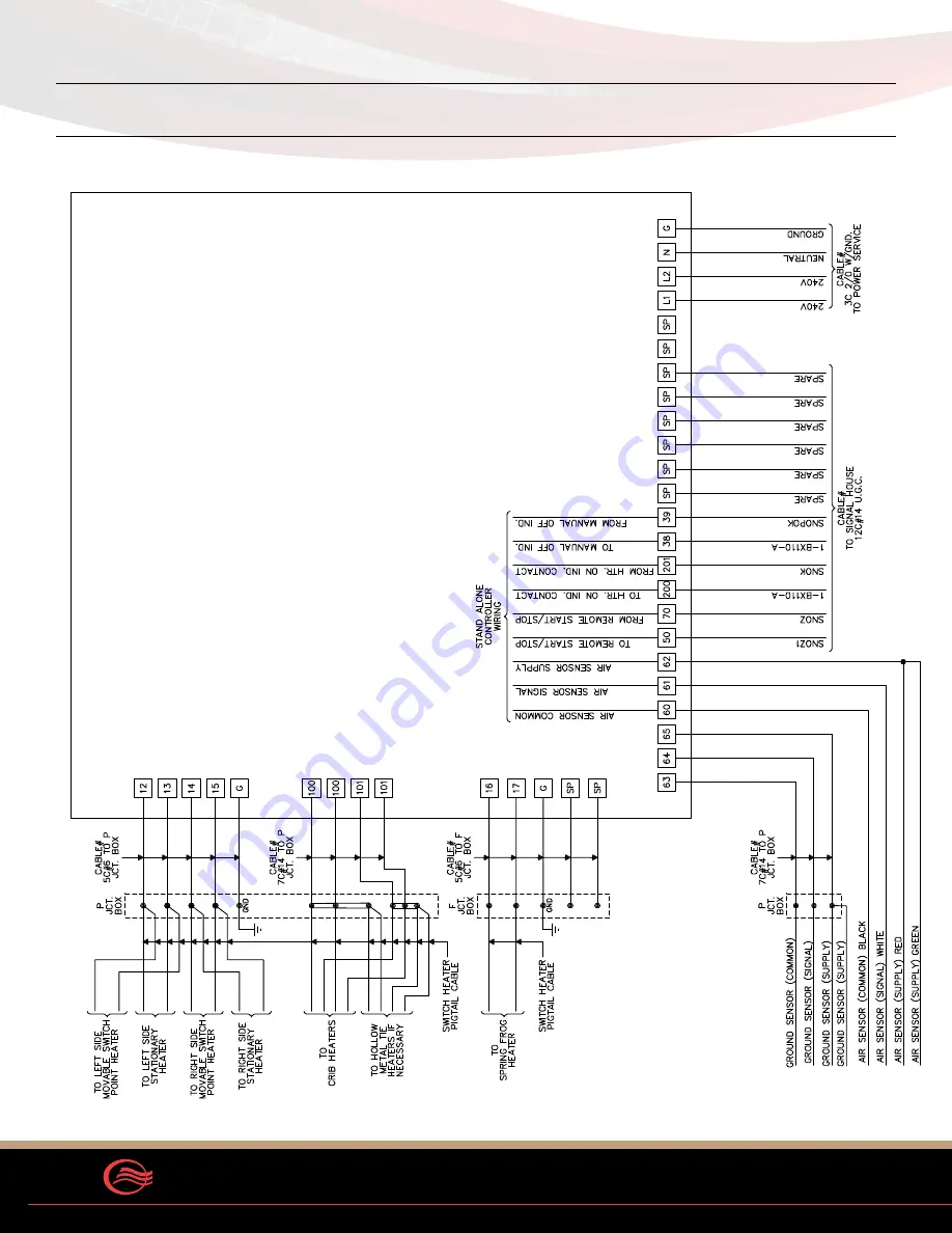
Page 32: ...traxTM 1 855 244 3128 Fax 1 303 979 7350 sales fastraxind com www fastraxind com 32 H SYSTEM WIRING DIAGRAMS H 1 STAND ALONE CONTROL PANEL WIRING DIAGRAM 1 NO 9 10 OR 11 SWITCH SPRING FROG HEATING SYS...
Page 33: ...CCI Thermal Technologies Inc 33 H 2 STAND ALONE CONTROL PANEL WIRING DIAGRAM 2 NO 9 10 OR 11 SWITCH SPRING FROG HEATING SYSTEM...
Page 34: ...FastraxTM 1 855 244 3128 Fax 1 303 979 7350 sales fastraxind com www fastraxind com 34 H 3 STAND ALONE CONTROL PANEL WIRING DIAGRAM 1 NO 14 15 OR 16 SWITCH SPRING FROG HEATING SYSTEM...
Page 35: ...CCI Thermal Technologies Inc 35 H 4 STAND ALONE CONTROL PANEL WIRING DIAGRAM 1 NO 20 OR 24 SWITCH SPRING FROG HEATING SYSTEM...
Page 36: ...FastraxTM 1 855 244 3128 Fax 1 303 979 7350 sales fastraxind com www fastraxind com 36 H 5 STAND ALONE CONTROL PANEL WIRING DIAGRAM 1 NO 20 OR 24 SWITCH MOVABLE POINT FROG HEATING SYSTEM...
Page 37: ...CCI Thermal Technologies Inc 37 H 6 MASTER CONTROL PANEL WIRING DIAGRAM UP TO 4 FASTRAX EXTENSION PANELS...
Page 38: ...FastraxTM 1 855 244 3128 Fax 1 303 979 7350 sales fastraxind com www fastraxind com 38 H 7 EXTENSION CONTROL PANEL WIRING DIAGRAM 1 NO 20 OR 24 SWITCH MOVABLE POINT FROG HEATING SYSTEM...
Page 39: ...CCI Thermal Technologies Inc 39 H 8 MASTER CONTROL PANEL WIRING DIAGRAM UP TO 8 FASTRAX EXTENSION PANELS...
Page 40: ...FastraxTM 1 855 244 3128 Fax 1 303 979 7350 sales fastraxind com www fastraxind com 40...
Page 41: ...CCI Thermal Technologies Inc 41 H 9 EXTENSION CONTROL PANEL WIRING DIAGRAM 1 NO 9 10 OR 11 SWITCH SPRING FROG HEATING SYSTEM...
Page 42: ...FastraxTM 1 855 244 3128 Fax 1 303 979 7350 sales fastraxind com www fastraxind com 42 H 10 EXTENSION CONTROL PANEL WIRING DIAGRAM 2 NO 9 10 OR 11 SWITCH SPRING FROG HEATING SYSTEM...
Page 43: ...CCI Thermal Technologies Inc 43 H 11 EXTENSION CONTROL PANEL WIRING DIAGRAM 1 NO 14 15 OR 16 SWITCH SPRING FROG HEATING SYSTEM...
Page 44: ...FastraxTM 1 855 244 3128 Fax 1 303 979 7350 sales fastraxind com www fastraxind com 44 H 12 EXTENSION CONTROL PANEL WIRING DIAGRAM 1 NO 20 OR 24 SWITCH MOVABLE POINT FROG HEATING SYSTEM...
Page 45: ...1 Side View of a Typical Junction Box Installation Figure H 13 2 Fastrax FC Insulated Connectors Used For Wire Connection In Junction Box Table H 13 1 Insulated Connector Torque Strip Chart Wire Size...
Page 46: ...nduit Installation Breather Drain Installed 3 4 NPT For Fastrax FA375 PC Connector Entry For Rail Crib Spring Frog and or Crib Heaters For Movable Point Frog Typical Of 9 Figure H 14 1 Top View of Jun...
Page 47: ...tchBlade Heater Figure H 14 3 No 20 or 24 SwitchBlade Heater Running Rail Connections Left and Right SwitchBlade Heaters At Rear Junction Box 7C 14 U G Cable From Stand Alone or Extension Panel Fastra...
Page 48: ...om Stand Alone or Extension Panel 3C 12 Cable From SwitchBlade Heaters 750 Watts Each for Movable Point Frog Plate 2C 10 Cable From 2 SwitchBlade Heaters for Movable Point Frog Wing Rail Figure H 14 5...
Page 49: ...nnector provided with the sensor connect the wires as shown in Figure H 15 2 Figure H 15 1 FGSP1A Ground Snow Sensor Figure H 15 2 FGSP1A Junction Box Wire Connections Table H 15 1 Wire Descriptions W...
Page 50: ...OURS HOURS HOURS NOTES OPERATION CHECKOUT INSTRUCTIONS QUALIFIED PERSONNEL ONLY 2 PUSH GREEN START WAIT FOR PANEL TO ENERGIZE CHECK FULL POWER ON PILOT PUSH STOP 5 USING FREEZE SPRAY AND WATER TEST FA...
Page 51: ...seconds the module will go into fault Check that the pilot light on dead front panel turned off Wait 8 10 seconds the GFI will reset Record ground fault test data below With dead front open turn disc...
Page 52: ...breakers and turn panel on Full Power At master panel record main load Ground fault modules are factory set No adjustments necessary To view trip set point open plastic cover hinges up Push R button...
Page 53: ...HM AMP VOLT NOTE NOTES FORM 0004ET TERMINAL NUMBERS 1 Position Facing switch point left or right hand heater PROJECT LOCATION HEATER CIRCUIT READINGS 2 Complete REF OHM column immediately before insta...
Page 54: ...ation Of Heaters Common Parallel Circuit Readings HEATER COMBINATIONS WATTAGE OHMS AMPS OHMS AMPS OHMS AMPS 1 2 200W 1 4 600W 6 800 8 5 28 3 33 9 14 2 52 9 11 3 1 2 200W 1 5 800W 8 000 7 2 33 3 28 7 1...
Page 55: ...full power is applied the green Full Power On indicating light will be illuminated 4 The integrated control and sensor system will continue to monitor the environment until no further snowfall is det...
Page 56: ...to the off position Automatic control will not operate again until the disconnect is returned to the on position For normal automatic control leave disconnect in the on position I 4 ADDITIONAL FEATUR...
Page 57: ...during the hold time operation either full or 25 power maintenance cycle if new snow falls and the ambient temperature falls below 38 F the automatic control is re initiated and full heating operation...
Page 58: ...main off The system will continue to try and reset every 5 minutes until it resets or an operator repairs the damaged switch heater or associated wiring If the system is running multiple switches or f...
Page 59: ...Dist Block Primary 120 Pwr Dist Block Secondary 45 Circuit Breakers Heater And Control Loads 17 7 STANDARD EQUIPMENT SELECTION I 10 SWITCHBLADE HEATING Contact Fastrax or review the bill of material f...
Page 60: ...heaters automatically return to full output J 2 INSTALLATION PROCEDURE Note Do not operate heaters at voltages in excess of that stamped on the heater Excess voltage will shorten heater life 1 0 SWITC...
Page 61: ...azard of severe shock Disconnect all power to heaters before servicing or replacing heaters Only qualified personnel trained in electrical equipment service should perform maintenance on switch heatin...
Page 62: ...62 NOTES...
Page 63: ...ficient heat transfer on rail equipment and components for the coldest environments In addition to heaters Fastrax manufactures fully automatic energy saving controls to complete the rail heating syst...