CCM12 CANbus
User Manual
13
9M02-7717-A001-EN
Version 3.0
3.
CANbus Operation
3.1
CANbus Redundant Controllers for Safety-Relevant Applications
The two CANbus interfaces are designed to operate in redundant fashion, so as to meet the requirements for
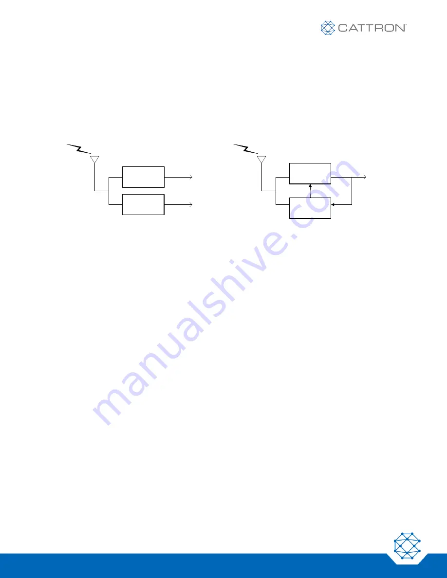
safety-relevant applications. Two different configurations are supported, as illustrated in Figure 10.
Figure 10: Two CANbus redundant operation
3.1.1 Parallel Operation
In parallel operation, the two processor/CANbus controllers operate independently from each other. They perform
similar processing on received RF telegrams, so the same CANbus data frames are sent from both of them. In
this configuration, it is up to the receiving nodes to validate the CANbus frames by comparing the master and
slave sides.
•
Node IDs
–
The two CANbus controllers are assigned different node IDs so they can be connected to the
same bus; the CCM12 actually appears as two different nodes running in parallel. The slave node ID equals
the master node ID + 1.
•
Received Data Frames
–
This redundant scheme works for transmit data frames only. The received data
frames (RPDO for CANopen, Rx PGN for J1939) are ignored by the slave controller.
•
Network Parameters
–
The master and slave controllers can be configured with different network
parameters by the network master. For example, in CANopen, one can be programmed for asynchronous
transmission and one for synchronous transmission. By default, the parameters are the same.
For applications where no redundancy is required, the master controller shall be used; the slave controller can be
left floating.
3.1.2 Cross-Monitored Operation
In cross-monitored operation mode, both processors perform the same processing on the received RF telegrams,
but CAN frames are sent by the master controller only. The slave reads back the frames transmitted by the
master controller for comparison. In addition, the slave processor reports to the master at regular intervals with
Monitoring Status Heartbeat messages so the master can double-check that the slave performs its verification
activity properly.
To
CANbus
Tx
frames
Heart
beat
Master
processor &
CANbus
controller
To
CANbus
RF telegrams
from OCU
To
CANbus
RF telegrams
from OCU
(a) Parallel Operation
(b) Cross-Monitored Operation
Slave
processor &
CANbus
controller
Master
processor &
CANbus
controller
Slave
processor &
CANbus
controller
Summary of Contents for CattronControl CCM12
Page 1: ...CCM12 CANbus User Manual ...


