background image

RS232C Communication Kit

4

RS board

Lower body
of operation unit

Socket

RS board

Circuit board

Plug in

Plug in

Connector cable

1-2) Assembling RS232C communication kit

1-2-a) Installing RS board 

4

 in

operation unit

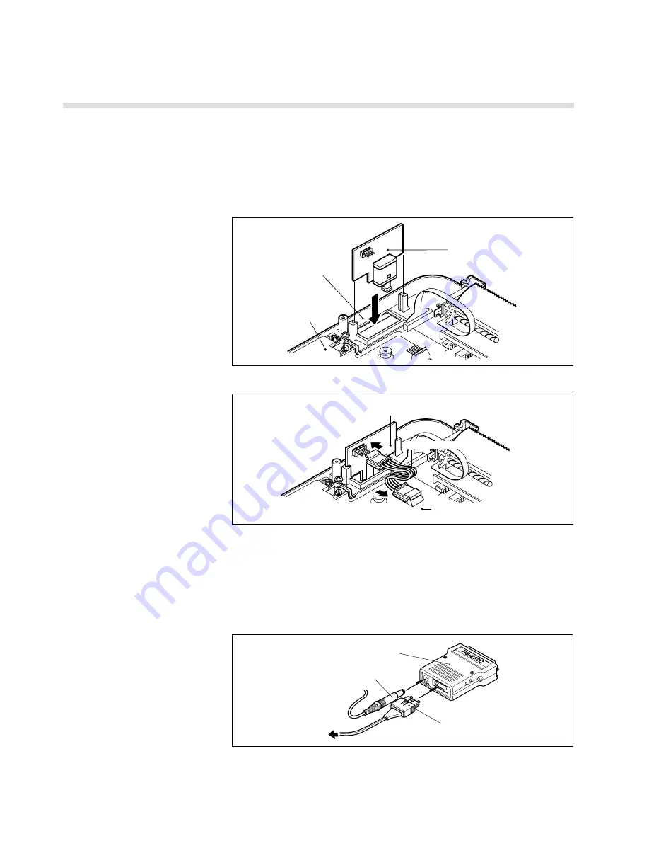
Remove the 8 screws that are holding the upper body on the rear panel of

the operation unit.  Open the unit's upper body as shown in the figure
below.

Referring to the figure, place the RS board so that its mounting holes are

aligned with mounting holes in the unit and the black optical cable
connector is located at the rear end of the unit.  Secure the board with the 2
screws supplied.

Connect the board to the unit via the connector cable supplied.

KIS-00RC000-P

DC

  IN

OU

T

IN

5V

Optical cable connector

Converter

AC Adapter connector

To operation unit

1-2-b) Connecting optical cable

to operation unit

Close the upper body and secure it with the 8 screws.

• Remove the covers from the optical connector and converter.  Insert the

optical cable connector and the AC Adapter connector into the converter

socket with the correct orientation. (If the optical cable connector is badly

oriented, it will not plug into the converter.)

Summary of Contents for ergociser RS232C

Page 1: ...RS232C Communication Kit Instruction Manual For Model EC 1500...

Page 2: ...ion 1 1 Checking components in the package 3 1 2 Assembling RS232C communication kit 4 1 2 a Installing RS board 4 in operation unit 4 1 2 b Connecting optical cable to operation unit 4 1 2 c Connecti...

Page 3: ...ents in the package 1 Preparation Note 1 Return to the distributor the User Registration Card attached to the warrantee Answers to questions written in the inquiry slip and loading of the sample progr...

Page 4: ...e unit and the black optical cable connector is located at the rear end of the unit Secure the board with the 2 screws supplied Connect the board to the unit via the connector cable supplied K I S 0 0...

Page 5: ...2 c Connecting procedure Remove the caps A B connect the optical cable connector to the operation unit optical cable connector Fix both caps A B when it s unused Secure the optical cable on the handle...

Page 6: ...ditions and once per second when you are exercising Since the contents of the LCD differs according to setting exercise conditions and during exercise the content of data output also differs The EC 15...

Page 7: ...4 digit numeric Elapsed time Higher 2 digits minute Lower 2 digits second 6 4 digit numeric Calorie consumption 10 3 digit numeric Wattage 13 2 digit numeric Pedal torque x 10 15 3 digit numeric Pulse...

Page 8: ...character code numeric code CR code format shown in example below from an external computer setting your exercise conditions Example K6CR Selects Auto Training Character Code Function A Age up to 2 di...

Page 9: ...utton initializing the EC 1500 Before externally controlling the EC 1500 first implement the reset command When using BASIC do as follows TX r PRINT 1 TX The computer may send the code r CR LF The EC...

Page 10: ...1 Exercise Pattern Interval Training TGWATT VAL MID RX 2 3 Set wattage Isopower Training Pressing the ADV button puts the EC 1500 into exercise status As with 2 4 c sending the g CR code duplicates th...

Page 11: ...nceled in the following ways The warm up is the function that increases the pedal torque gradually for 3 minutes after starting the exercise 1 While using isopower constant wattage set the watt value...

Page 12: ...IF A A OR A a THEN GOSUB PBADV 110 IF A S OR A s THEN END 120 GOTO 70 130 PBADV 140 TX g PRINT 1 TX 150 INPUT 1 RX 160 IF RX a GOTO 150 170 RETURN Obtain data from the EC 1500 and display it on the sc...

Page 13: ...RX 21 2 260 LTPLS VAL MID RX 18 3 270 TGTM VAL MID RX 16 2 280 WEIGHT VAL MID RX 13 3 290 TGTQ VAL MID RX 11 2 10 300 PROF VAL MID RX 10 1 310 SEX VAL MID RX 9 1 320 TGPLS VAL MID RX 6 3 330 INTVL0 V...

Page 14: ...ING TGTQ 700 GOTO PEND 710 CONST 720 LOCATE 1 1 PRINT ISOPOWER TRAINING 730 LOCATE 3 2 PRINT AGE PRINT USING AGE 740 LOCATE 3 3 PRINT PULSE LIMIT PRINT USING LTPLS 750 LOCATE 3 4 PRINT SET WATTAGE PRI...

Page 15: ...ATE 3 7 PRINT PULSE RATE PRINT USING HR 1190 LOCATE 3 8 PRINT CADENCE PRINT USING CDC 1200 IF PFL 0 THEN LOCATE 42 3 PRINT PFL PRINT USING PFL 1210 IF MOU 0 THEN LOCATE 42 4 PRINT MOU PRINT USING MOU...

Page 16: ...ER 1530 GOTO WRITETGTM 1540 IF N 5 GOTO 1570 1550 IF MODE 4 GOTO 1570 1560 GOTO WRITETGTQ 1570 LOCATE 6 12 PRINT SPC 30 1580 LOCATE 6 12 PRINT SPC 30 GOTO ENTER 1590 WRITEWT 1600 IF VAL A 999 OR VAL A...

Page 17: ...TETGTM 1880 IF VAL A 99 OR VAL A 0 THEN GOTO OVER 1890 TX C A GOTO WRITEDATA 1900 WRITEDATA 1910 GOSUB DATAOUT 1920 CLS GOTO 220 1930 OVER 1940 LOCATE 6 13 PRINT SPC 30 GOTO 1410 1950 1960 1970 1980 R...

Page 18: ...30 187 B 2360 FOR I 97 TO 177 STEP 10 LINE 25 I 30 I NEXT I 2370 FOR I 60 TO 600 STEP 30 LINE I 187 I 190 NEXT I 2390 LOCATE 0 23 PRINT 60 2400 LOCATE 0 18 PRINT 100 2410 LOCATE 0 13 PRINT 140 2420 RE...

Reviews: