25. Support the Inlet Manifold from the under side and align
manifold with Crankcase Guide Pins. Keep manifold
aligned to avoid damaging Plungers. To assure alignment
use two M16 studs (PN 88902) as guides and remove
when manifolds are in place. Apply Loctite 242 to Hex
Head screw threads and thread in hand tight. Torque in
sequence to specification in torque chart.
26. Lubricate the exposed O-Rings on the V-Packing Spacer
and valve chamber walls.
27. Support the Discharge Manifold from the under side and
align with Inlet Manifold holes. Apply Loctite 242 to HSH
screw threads and thread in hand tight. Torque in se-
quence to specifications in torque chart.
SERVICING THE PLUNGERS
Disassembly
1. To secure the plungers, it is necessary to remove both the
Discharge and Inlet Manifolds. Follow disassembly proce-
dures for REMOVING THE DISCHARGE MANIFOLD and
REMOVING THE INLET MANIFOLD.
2. Remove the Seal Retainers from each Ceramic Plunger.
3. Remove the Adapter Front Seal Retainer from the Rear
Seal Retainer.
4. Remove the used Wick and install new wick.
5. Replace Front and Rear Seal Retainer.
6. Loosen Plunger Retainer 4 to 5 turns. Push Plunger to-
wards Crankcase until Plunger Retainer pops out.
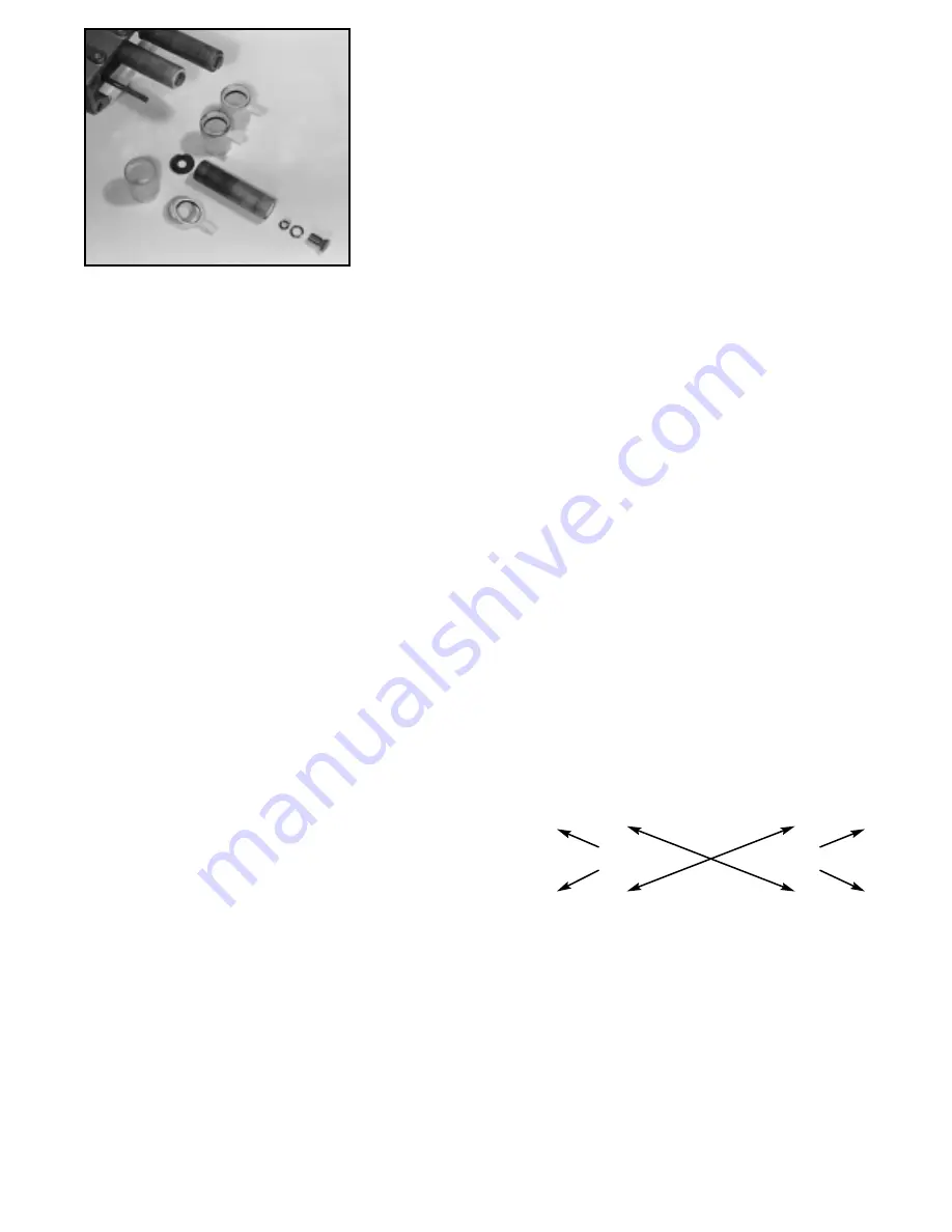
7. Unscrew and remove Plunger Retainer, Gasket, O-Ring,
Back-up-Ring, Ceramic Plunger, Keyhole Washer and
Barrier Slinger.
Reassembly
1. Replace Barrier Slinger then Keyhole Washer on each
Plunger Rod.
2. Carefully examine each Plunger for scoring or cracks and
replace if worn.
NOTE: Ceramic Plunger can only be installed one di-
rection (front to back). Do not force onto rod.
3. Examine Gasket, O-Ring and Back-up-Ring on Plunger
Retainer and replace if cut or worn. Lubricate O-Ring for
ease of installation and to avoid damaging O-Rings. First
install Gasket, O-Ring then Back-up-Ring.
4. Apply a small amount of Loctite 242 to exposed threaded
end and thread Plunger Retainer onto Plunger Rod.
Torque per chart.
5. Slip Seal Retainers over Plungers. Insert smaller diameter first.
NOTE: Line up Wicks with the oil holes in the
Crankcase and tabs down towards the Oil Pan.
NOTE: No wick is used on 6747.
6. Rotate Crankshaft by hand so the two outside Plungers
are extended equally.
7. Carefully slide Inlet Manifold over Plungers and press
towards Crankcase. Keep manifold aligned to avoid dam-
aging Plungers. To assure alignment use two M16 studs
(PN 88902) as guides and remove when manifolds are in
place.
8. Replace four (4) Hex Head Screws and two (2) Hex Nuts
and torque per chart.
9. Lubricate the exposed O-Rings on the V-Packing Spacer
and valve chamber walls and carefully slip Discharge
Manifold over Plungers and snug up to the Inlet Manifold.
10. Hand tighten the outer top two (2) Hex Socket Head Screws
first. Then hand tighten the remaining six (6) Hex Socket
Head Screws. Torque in sequence to specifications in
torque chart.
TORQUE SEQUENCE
SERVICING THE CRANKCASE SECTION
1. While Manifolds, Plungers and Seal Retainers are re-
moved examine Crankcase Oil Seals for wear.
2. Check oil level and check for evidence of water in oil.
3. Rotate Crankshaft by hand to feel for smooth bearing
movement.
4. Check for any signs of leaking at Rear Cover, Drain Plug
and Bubble Gauge.
5. Examine Crankshaft Oil Seals externally for drying, crack-
ing or leaking.
6. Consult CAT PUMPS or your local distributor if Crankcase
service is required. Refer to Tech Bulletin 035.
See Section V of the Plunger Pump Service Video for
additional information.
5
1
3
7
0
0
0
0
0
0
0
0
8
4
2
6
Complete plunger arrangement


