CAT Pumps 1XP Series Installation, Operational And Repair Manual Download Page 14

14

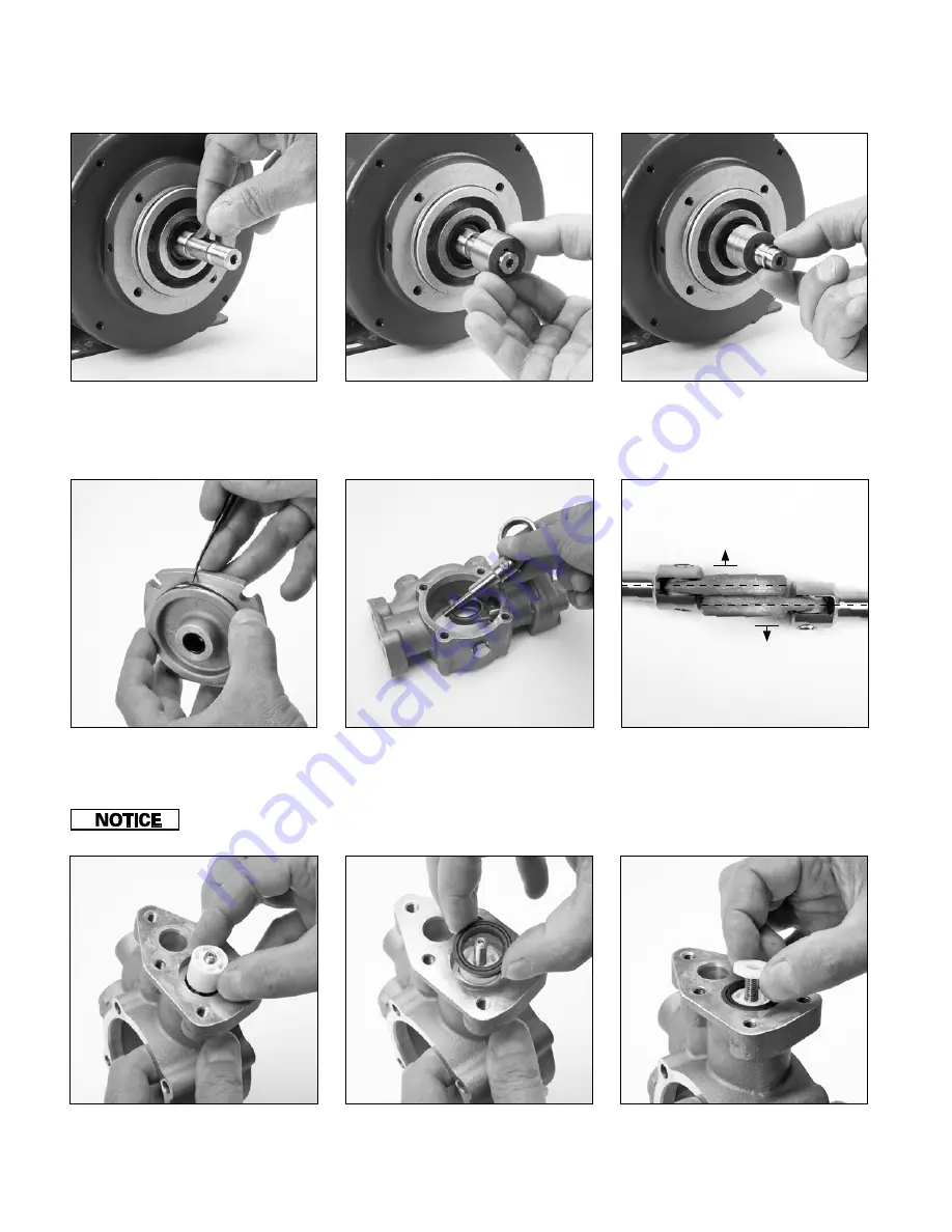
6.11   Install plunger rod/connecting rod  

assembly through large opening in 
crankcase body (1). 


Be careful not to damage the bushing ID in the case, as the plunger rod thread passes through the bushing.

6.12   Protruding cast face of connecting 

rods should face away from each other 
inside crankcase (1).  


Out

Eliminates 

Interference

Out

6.15   Install inlet valve (20) with flat side 

down onto plunger (21).

6.14   Lightly lubricate and install high 

pressure seal (22) with v-groove facing 
up over ceramic plunger (21).

6.13   Install ceramic plunger (21) with 

recessed face away from crankcase. 

Pump Reassembly continued

6.10   Lubricate and install o-ring (6) onto 

bearing cover (5). 


6.9   Install retaining ring (7) into snap  

ring groove on motor shaft to secure 
cam (8). (Keyed Shaft only).

6.7   Lubricate and install woodruff key (9) 

into motor shaft keyway. (Keyed Shaft 
only).

6.8   Lubricate and install cam (8) over  

motor shaft and key. Position cam (8) 
so stamped cam ID number is facing 
pump. (Keyed Shaft only).

Summary of Contents for 1XP Series

Page 1: ...1XP Series Plunger Pump Installation Operational and Repair Manual www catpumps com Product Quality Reliability and Support You Expect ...

Page 2: ...t 8 Exploded view 9 Pump disassembly 10 12 Pump reassembly 13 16 DC Motor 8136 brush replacement 17 Stopping for long periods 17 i e long term and or winterization Restarting system 17 Torque specifications and repair tools 18 Preventative maintenance 18 Troubleshooting 18 i e problem cause solution Flow and Pressure 19 Cat Pumps Warranty 20 IMPORTANT SAFETY INSTRUCTIONS It is the responsibility o...

Page 3: ...gger lock safety latch to avoid accidental high pressure operation and personal injury or property damage 3 Do not check for leaks with hand Use a piece of cardboard to check for leaks 4 Review cleaning procedures to minimize heavy back blasting 5 Wear adequate safety equipment and clothing when operating high pressure sprayer Never use high pressure spray with bare feet or exposed skin and always...

Page 4: ...liquid 2 Clean equipment in a well ventilated area 3 Disposal of solvents to be in accordance with local state and federal regulations D OPERATING BEYOND SPECIFICATIONS HAZARD Do not operate the pump outside the specifications of individual pump data sheet or service manual Operating the pump under these conditions could result in personal injury and property damage 1 Do not operate the pump faste...

Page 5: ...arings or reduce horsepower 1 Rotate pump crankshaft before starting to ensure shaft and bearings are moving freely 2 Ensure pulleys are properly sized 3 Periodically replace belts to assure full horsepower transmission 4 Ensure center distance dimensions between pulleys is correct C BY PASS OPERATION HAZARD Do not operate the pump in by pass for extended lengths of time Operating the pump under t...

Page 6: ...25 03DCT 1XP150 1XP150 031 1XP150 051 1XP150 071 1XP150 101 1XP150 03DC 1XP150 03DC2 1XP150 03DCT 1XP180 1XP180 071 1XP180 101 1XP200 1XP200 031 1XP200 051 1XP200 071 1XP200 101 1XP200 03DC 1XP200 03DC2 1XP200 03DCT Stamped Cam ID number See Chart Pump and Motor Installation Technical Features Pump Models and Pump Motor Assemblies There are eight 8 cams available for the 1XP Series Pumps Each cam ...

Page 7: ...ion 1 5 Install inlet water hose to center 3 8 NPT port on pump labeled INLET Inlet Port Electrical power connection 1 3 Connect to power source for AC induction motors 8133 8135 and 8147 115 208 230VAC 1 4 Connect to power source for DC permanent magnet motor 8136 8139 120 Volt rectified and 8138 240 Volt rectified Power Cord Connection NOTE Standard pump to motor mounting is shown in figure 1 5 ...

Page 8: ...206 S Valve Discharge 2 26 76865 S Spring Valve 06 13 2 27 76069 PVDF Retainer Valve 2 28 76555 AL Assembly Plunger ConnectingRod Includes plungerrod connectingrod wristpin 2 29 76227 NY Kit InletValve Includes items16 17 18 19 20 1 30 76218 FPM Assembly DischargeValve Includes items23 24 25 26 27 1 31 76219 FPM Kit SealandO ring Includes items6 10 11 12 15 22 1 32 76127 Kit BrushReplacement 8136o...

Page 9: ...9 13 14 22 22 21 19 17 26 24 30 15 1 15 27 25 23 14 20 28 18 16 13 7 3 4 5 6 9 11 8 10 12 ACMotor ThreadedShaft DCMotor KeyedShaft ACMotor KeyedShaft Exploded View ...

Page 10: ...uipmentwhileenergized Electricitycancausepersonalinjury deathorpropertydamage 1 Adhere to Lock Out and Tag Out procedures for electrical equipment 2 Before commencing pump service turn power supply off 3 Keep water away from electrical outlets and electrical devices 4 Electrical components must be installed by a qualified electrician to avoid risk of electrocution ToolsRequired 1 4mm M4 Allen Wren...

Page 11: ...move and inspect shaft seal 10 from motor flange Do not scratch or damage motor shaft surface 5 10 Remove and inspect shaft seal 10 from motor flange Do not scratch or damage motor shaft surface 5 9 Insert two 2 flat tip screw drivers between flange and pry shaft seal away from motor 5 8 Unthread threaded cam from motor shaft For Threaded Shaft Units Ifoldshaftsealcannotbe removed itmayrequireremo...

Page 12: ...re identical in both cylinder heads 5 18 Remove and inspect nut 16 washer 17 spacer 19 spring 18 and inlet valve 20 5 19 Remove and inspect ceramic plunger 21 and high pressure seal 22 from crankcase body 1 5 20 Remove and inspect connecting rod plunger rod and wrist pin assembly 5 15 Insert the short end of an allen wrench to remove discharge valve assembly 5 14 Use a 5mm allen wrench to remove f...

Page 13: ...lange by sliding over motor shaft Center between shaft seal bore and back of the slinger seal bore 6 2 Lubricate and install motor flange o ring 12 onto the motor flange Loctite and 242 are registered trademarks of the Henkle Corporation 6 5 Hand thread cam 8 with stamped ID number and small holes facing pump clockwise 6 6 Use spanner wrench and 1 2 open wrench to tighten cam 8 NOTE Apply Loctite ...

Page 14: ...o plunger 21 6 14 Lightly lubricate and install high pressure seal 22 with v groove facing up over ceramic plunger 21 6 13 Install ceramic plunger 21 with recessed face away from crankcase Pump Reassembly continued 6 10 Lubricate and install o ring 6 onto bearing cover 5 6 9 Install retaining ring 7 into snap ring groove on motor shaft to secure cam 8 Keyed Shaft only 6 7 Lubricate and install woo...

Page 15: ...e over the spring 26 6 19 Apply Loctite 242 to M6 threads on plunger rod Thread nut 16 onto M6 threads of plunger rod and torque to 25 in lbs Loctite and 242 are registered trademarks of the Henkle Corporation 6 22 Place tapered side of seat 24 towards retainer 27 and snap into place 6 23 Lubricate and install o ring 23 to seat 24 Repeat for second valve assembly 6 24 Press discharge valve assembl...

Page 16: ...mmwrenchtoinstalldrainplug 3 into bottom port of crankcase body 1 6 28 With bearing cover 5 removed position crankcase body 1 onto motor while lining up the connecting rods 28 with the cam 8 Note Make sure the connecting rods are loose on cam 1 3 4 5 2 6 29 Hand thread four 4 M6x75 button head screws 4 Use a 4mm allen wrench to torque to 48 in lbs in sequence as shown Note Lubricate o ring on bear...

Page 17: ...er remove white retaining clip 7 3 Remove wire lead from small opening in motor housing 7 4 Blow out dust that may accumulate in opening of motor 7 5 Repeat steps 7 1 to 7 4 to remove second wire lead REASSEMBLY 7 6 Position wire lead into opening of motor with brush and attaching spring down into opening with brass end facing up 7 7 Place white retaining clip over wire lead and snap into place 7 ...

Page 18: ... Pumps parts or kits when performing repairs Troubleshooting The troubleshooting table has been provided to assist in defining problems that may arise then giving probable causes to look for and finally providing possible solutions to the problem at hand Problem Probable Causes Solutions Low pressure Worn nozzle Replace with proper size nozzle Worn seals Install new seal kit Increase frequency of ...

Page 19: ...CT 2 3 150 4 0 1XP200 03DC 1XP200 03DCT GPM Max PSI Pump Assembly SFA HP 0 40 600 1XP050 031 4 2 2 1 1 3 0 60 500 1XP075 031 0 70 500 1XP085 031 0 80 450 1XP100 031 1 400 1XP125 031 1 2 325 1XP150 031 1 70 250 1XP200 031 0 30 1000 1XP050 051 8 2 3 8 1 2 0 60 1000 1XP075 051 0 70 1000 1XP085 051 0 75 800 1XP100 051 1 800 1XP125 051 1 2 600 1XP150 051 1 70 450 1XP200 051 0 75 1000 1XP100 071 10 0 4 ...

Page 20: ...Cat Pumps shall not be liable for defects or failures resulting from improper or lack of maintenance lack of proper crankcase lubrication failure to supply adequate liquid to pump pumping materials below 5 pH or above 9 pH above 500 cps general wear and tear or any malfunction damage or wear caused by faulty installation misapplication misuse accident excessive abrasion corrosion freezing or heat ...

Reviews: