background image


Page 59


Mark All 


Use this option to mark all the saved recordings. 


Exp Point Calc 


Select to calculate the Exposure Point Total of the combined marked recordings. 


All logs must be of the same mode for this function excluding single axis and 
custom mode recordings which cannot be combined and therefore will not work 
under the Exposure Point calculator.  The examples below show mismatched 
modes and single axis error messages: - 


Press the 

OK

 key to return to the previous screen. 


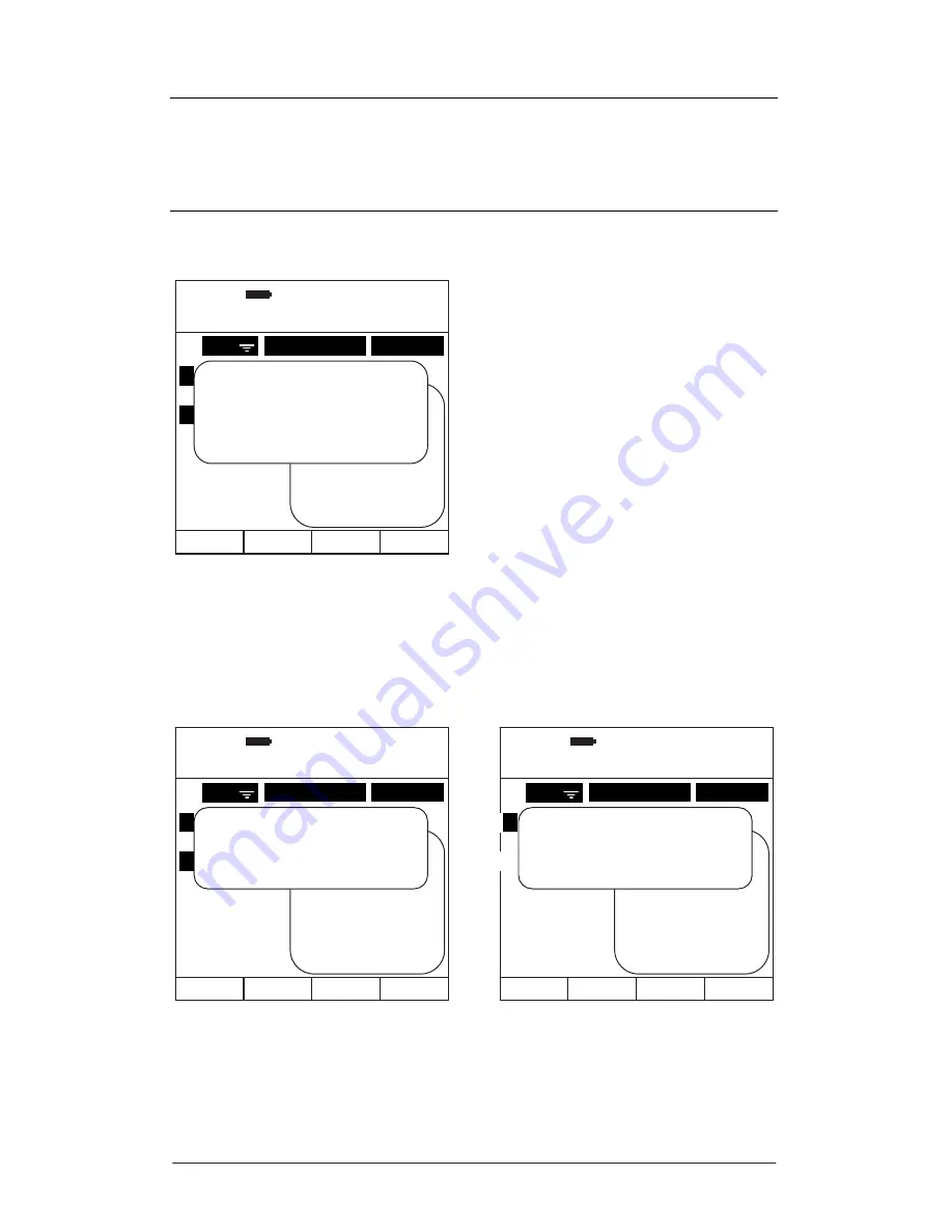
Figure 60 – Exposure Point Total Calculator


Figure 61 – Exposure Point Calculator Error Messages


09:32:30

26:08:11

MARK LOGS


Select file to mark 

EMPLOYEE 

DATE 


12 
18 

Robert 
Lee 
Simon 
Emily 
Mike 

1.


2. 

3.


4. 
5. 

REC 

1.  Mark All 
2.  A(8) Calc 
4.  VDV Calc 
5.  Print Marked 
6.  Delete Marked 
7.  Sort 
 

Exposure Point Total


201 Points


Action Value Exceeded 


Press OK

09:32:32

26:08:11

MARK LOGS 


Select file to mark 

EMPLOYEE 

DATE 


12 
18 

Robert 
Lee 
Simon 
Emily 
Mike 

1.


2. 

3.


4. 
5. 

REC 

1.  Mark All 
2.  A(8) Calc 
4.  VDV Calc 
5.  Print Marked 
6.  Delete Marked 
7.  Sort 
 

All logs must be


the same mode 


Press OK 

09:32:34

26:08:11

MARK LOGS 


Select file to mark 

EMPLOYEE 

DATE 


12 
18 

Robert 
Lee 
Simon 
Emily 
Mike 

1.


2. 
3. 
4. 
5. 

REC 

1.  Mark All 
2.  A(8) Calc 
4.  VDV Calc 
5.  Print Marked 
6.  Delete Marked 
7.  Sort 
 

Single axis logs


cannot be combined 


Press OK 

Summary of Contents for Excieo GA2005H

Page 1: ......

Page 2: ......

Page 3: ......

Page 4: ...www castlegroup co uk Castle Excieo Vibration Meter Operating Manual Excieo GA2005H HARM Vibration Meter Excieo GA2005S Single Axis Vibration Meter Excieo GA2005M Multi Function Vibration Meter...

Page 5: ...YO11 3UZ UK Copyright Castle Group Ltd 2012 All rights reserved No part of this publication may be reproduced stored in a retrieval system or transmitted in any form or by any means electronic mechan...

Page 6: ...more about our Competent Persons training course for Human Vibration You can visit www castletrainingacademy com to find out more Castle Group has become the leading supplier of solutions for health...

Page 7: ...bjects such as wire or metal particles to enter the unit Do not try to disassemble the instrument or attempt any repairs as this will invalidate your warranty Take a note of the condition of the instr...

Page 8: ...ibration Level 11 Frequency Weighting Filters 12 Under Range Overload Conditions 14 Under Range Condition 14 Overload Condition 14 Measuring Ranges 15 Vibration Exposure Points 15 CHAPTER 4 16 Getting...

Page 9: ...um Allowable Criterion Levels 47 Option 6 Filters 48 Option 7 Accelerometer 49 Option 1 Page 2 Correction Factor 50 Option 2 page 2 Personal Exposure 51 CHAPTER 6 52 Recording Operation 52 Ending a Re...

Page 10: ...10mV 95 Transducer 100mV 97 Transducer 1000mV 99 Level Ranges 100 Whole Body Vibration Mode WBV 100 Transducer 100mV 100 Transducer 1000mV 100 Custom Vibration Mode CUSTOM 101 Acceleration Transducer...

Page 11: ...verload 113 Size and Weight 113 Connections 114 Output 114 Wiring Configuration Signal Printer 9 Pin Lemo 114 AC Output 114 Printer 114 USB B Socket 114 Input 115 Wiring Configuration 5 Pin Lemo 115 B...

Page 12: ...re 25 HARM Personal Exposure Selection 32 Figure 26 HARM Display Screens with Personal Exposure On Off 32 Figure 27 Toggle Time History ON OFF 33 Figure 28 Time Interval Entry 33 Figure 29 Toggle Meas...

Page 13: ...ate Search 65 Figure 72 Create Search Entry Prompts 65 Figure 73 Save Search 66 Figure 74 Save Search Error Message 66 Figure 75 Delete Search 67 Figure 76 Memory Info 67 Figure 77 Templates 68 Figure...

Page 14: ...o view sample video clips www need2know4free com Dedicated to professionals in Health and Safety Environmental Compliance and Plant Maintenance Engineering Castle set out to help you in a way that sui...

Page 15: ...Surveillance Health Screening Air Sampling and Gas Detection Indoor Air Quality Airflow EMF Testing and Monitoring Portable Appliance Testing PAT General Compliance and Risk Assessment ENVIRONMENTAL C...

Page 16: ...ervices Castle Training Academy Competence and Compliance training is essentially all about obtaining the knowledge and skills required to get the job done This is precisely how Castle courses are set...

Page 17: ...he top of their game and are waiting to hear from you Have a look at our website or call on 01723 584250 Noise and Vibration COSHH Assessments Light Temperature EMF Assessments Environmental Monitorin...

Page 18: ...ygrometers Thickness meters Timers Vibration meters Vibration analysers Weighing equipment Castle Contract If peace of mind for equipment calibrations is important to you and it should be then check o...

Page 19: ...deduction is important then Rental could well be the way to go Go to our website to find the huge range of equipment we have available You might also like to make use of our ex rental purchase as a wa...

Page 20: ...ost measurement analysis and presentation of data can be done using this package VibdataPro allows seamless integration with word processing and spreadsheet packages enabling you to use your own stand...

Page 21: ...ieo usability straightforward GA2005S Single Axis Vibration Provided for general vibration applications where only filters relevant to machine monitoring are selectable for added simplicity Digital fi...

Page 22: ...rometer Type Output Voltage Operating Range Frequency Response Hand Arm 10mV g 500g 2 to 5000Hz 10 Whole Body KD1007 100mV g 50g 0 5 to 3000Hz 5 Whole Body KD1009 1000mV g 3 6g 0 1 to 125Hz 5 Single A...

Page 23: ...transducers for Whole Body Vibration both of which are available from Castle Group Ltd See page 80 for details to ensure your instrument has been setup correctly Where the Tri Axial accelerometers ava...

Page 24: ...k Position the accelerometer cable so that the orientation key is in line with the RED mark and then gently push the accelerometer cable into the instruments socket Figure 2 Attaching Accelerometers t...

Page 25: ...le and the best compromise must be achieved Measurement durations are not governed but as a rule of thumb use an absolute minimum time period of 5 minutes for Whole Body and 30 seconds for Hand Arm Vi...

Page 26: ...ion source and attaching the accelerometer to the stud Alternatively the stud may be adhered to the device rather than tapped with an adhesive that dries rigid Castle Group Ltd can supply a glue and s...

Page 27: ...n the figure below are used If this is not possible then choosing other axes orientation is permissible and will not affect your measured data In all cases it is strongly recommended to make notes on...

Page 28: ...he back to the chest of the operator Y Direction Vibration from the right side to left side of the operator Z Direction Vibration from the feet or buttocks to the head of the operator The filtering an...

Page 29: ...Page 10 Figure 5 Axis for Seated Operator Figure 6 Axis for Reclined Operator...

Page 30: ...ed the correct parameters The optimum range is generally the lowest range that can be selected that does not produce an overload condition for the process being monitored Where high levels of vibratio...

Page 31: ...erson present for the horizontal X Axis Wd Used for measurement of a seated standing or a reclined person for horizontal vibrations in the X and Y Axis We Applied when measuring rotational vibration i...

Page 32: ...y weighting For ease of use HARM and WBV display modes have set frequency weighting filters automatically applied to the measured vibration signal CUSTOM mode allows any combination of frequency weigh...

Page 33: ...in these circumstances is approximately 10dB lower than other display modes See Technical Specification for a complete list of Under Range triggering points Overload Condition An overload condition o...

Page 34: ...points exposure for a working day The vibration analysis software VibdataPro allows you to merge individual recordings and automatically calculate total exposure points It even colour codes the result...

Page 35: ...ailable the meter must be placed into Recording Operation see Recording Operation for more information and procedures When the meter is first switched on the meter defaults to Real Time Operation Your...

Page 36: ...Page 17 Keypad Layout Figure 7 Keypad Layout Soft Key 2 Soft Key 3 Soft Key 1 Soft Key 4 Left Arrow Right Arrow Record Stop Play Pause OK Back Light Alpha Numeric Keypad Power On Off Main Menu...

Page 37: ...Mode Screen Layout Current Display Mode Current Range Soft Key Options Axes Parameter Values Real Time Clock Displayed Parameter Battery Level Current Display Mode Current Range Axes Parameter Values...

Page 38: ...a longer battery life with your instrument it is strongly recommended you use Alkaline type batteries unplugging the transducer whilst not measuring may also prolong battery life To power the instrume...

Page 39: ...is disabled whilst the instrument is recording To preserve your data always turn your instrument off using the Power Key Your Excieo meter is equipped with a battery indicator to easily identify the a...

Page 40: ...you require by pressing the appropriate number on your keypad or press Soft Key 1 labelled CANCEL to cancel the operation and return to the previous screen Dedicated HARM and SINGLE axis meters do no...

Page 41: ...parameter screens is achieved using the Left and Right Arrow Keys The dominant axis is always identified by having the character displayed next to it In Single Axis mode or Cusotm mode either a single...

Page 42: ...arameter Display Screens Range 0 10 500 ms 2 09 00 40 26 08 11 Aeq HARM Range 0 10 500 ms 2 Duration 00 00 00 to change parameter Y Wh 0 124 X Wh 0 123 Z Wh 0 125 RESET SETUP MODE RANGE 09 00 42 26 08...

Page 43: ...Examples of the four parameter display screens for HARM are shown below Figure 14 HARM Range Selection Screens Range 1 0 5000 ms 2 09 01 46 26 08 11 Aeq HARM Duration 00 00 00 to change parameter Y Wh...

Page 44: ...lay mode are shown below HARM WBV SINGLE Figure 15 Default Setup Option Screens HARM WBV SINGLE 1 Time History OFF 2 Timer OFF 3 Results VS 4 Personal Exp ON 09 02 04 26 08 11 SETUP MORE EXIT 09 02 02...

Page 45: ...for more details Press 2 to save the current settings for the current display mode as a Template for future use See Saving As Templates Within Setup for more details Press Soft Key 4 labelled CANCEL...

Page 46: ...IT allows you to edit the settings of the template To delete the template press Soft Key 4 labelled DELETE If the TEMPLATE DETAILS screen is displayed then pressing Soft Key 1 labelled EXIT will retur...

Page 47: ...up to 15 characters for the template to be saved Use Soft Key 2 labelled NUMBER or LETTER to toggle the input between numbers and letters Press OK to accept and Save the Template or press Soft Key 1 l...

Page 48: ...s 23 59 59 hh mm ss Invalid entries will display an Out of range message and return the value to its previous state To delete errors use the Left Arrow Key Press Soft Key 1 labelled CANCEL to discard...

Page 49: ...maximum interval time permitted is 23 59 59 hh mm ss Invalid entries will display an Out of range message and return the value to its previous state To delete errors use the Left Arrow Key Press Soft...

Page 50: ...d therefore can only be viewed from a completed recording Press 1 on the keypad to toggle the display of Vector Sum ON OFF or press 2 to toggle the display of Dominant Axis ON OFF Press Soft Key 1 lab...

Page 51: ...ake any changes made The example screens below show how the display screens differ with setting Personal Exposure On or Off Figure 25 HARM Personal Exposure Selection 1 Personal Exp ON 09 05 12 26 08...

Page 52: ...is 23 59 59 hh mm ss Invalid entries will display an Out of range message and return the value to its previous state To delete errors use the Left Arrow Key Press Soft Key 1 labelled CANCEL to discard...

Page 53: ...e maximum interval time permitted is 23 59 59 hh mm ss Invalid entries will display an Out of range message and return the value to its previous state To delete errors use the Left Arrow Key Press Sof...

Page 54: ...ey can only be viewed from a completed recording Press 1 on the keypad to toggle the display of Vector Sum ON OFF Press 2 to toggle the display of Dominant Axis ON OFF Press 3 to toggle the display of...

Page 55: ...make any changes made The example screens below show how the display screens differ with setting Personal Exposure On or Off Figure 32 WBV Personal Exposure Selection 1 Personal Exp ON 09 08 12 26 08...

Page 56: ...d is 23 59 59 hh mm ss Invalid entries will display an Out of range message and return the value to its previous state To delete errors use the Left Arrow Key Press Soft Key 1 labelled CANCEL to disca...

Page 57: ...e maximum interval time permitted is 23 59 59 hh mm ss Invalid entries will display an Out of range message and return the value to its previous state To delete errors use the Left Arrow Key Press Sof...

Page 58: ...s display mode any of the above methods can be used and once selected the display parameters used for Real Time and Recording Operation are as follows Acceleration Aeq Amax Arms Pmax Velocity Veq Vmax...

Page 59: ...ometers tolerance and without applying high or low frequency roll off within the linear region specified Selection of the filter has immediate effect in Real Time Mode and is applied to any subsequent...

Page 60: ...nged then a screen prompt informs you to re calibrate your instrument to the new accelerometer being used Confirmation of having accepted that the new accelerometer must be calibrated with the new set...

Page 61: ...s 23 59 59 hh mm ss Invalid entries will display an Out of range message and return the value to its previous state To delete errors use the Left Arrow Key Press Soft Key 1 labelled CANCEL to discard...

Page 62: ...e maximum interval time permitted is 23 59 59 hh mm ss Invalid entries will display an Out of range message and return the value to its previous state To delete errors use the Left Arrow Key Press Sof...

Page 63: ...a completed recording VDV results are only recorded for metric units Press 1 on the keypad to toggle the display of Vector Sum ON OFF Press 2 to toggle the display of Dominant Axis ON OFF Press 3 to t...

Page 64: ...e selected the display parameters used for Real Time and Recording Operation are as follows Acceleration Aeq Amax Arms Pmax Velocity Veq Vmax Vrms Pmax Displacement Deq Dmax Drms Pmax Press 1 on the k...

Page 65: ...VDV Exposure Limit Value Enter the new value using the numeric keypad for example enter 0250 for a value of 2 50 The decimal point is applied automatically Use the Left Arrow key to delete unwanted in...

Page 66: ...lue Exposure Limit Value 149 54 dB dB Reference 1e 6 Exposure Action Value 119 99 dB Exposure Limit Value 119 99 dB Vibration Dose Value Exposure Action Value 129 54 dB Vibration Dose Value Exposure L...

Page 67: ...n Real Time Mode and is applied to any subsequent recordings Press 1 2 or 3 to activate the Filter selection for the axis required and then use the Left and Right Arrow Keys to scroll through the avai...

Page 68: ...tivity of 10mV g Press 2 for a sensitivity of 1000mV g If the sensitivity is changed then a screen prompt informs you to re calibrate your instrument to the new accelerometer being used Confirmation o...

Page 69: ...int is applied automatically Use the Left Arrow key to delete unwanted input or press the OK key to accept the inputted value An Invalid input will give an Out of Range error message the valid range i...

Page 70: ...ke any changes made The example screens below show how the display screens differ with setting Personal Exposure On or Off Figure 51 Custom Mode Personal Exposure Selection 1 Personal Exp ON 09 19 12...

Page 71: ...n on the display parameters By pressing the PAUSE Key on the keypad it is possible to view a snapshot of the data values at that point in time Use the Left and Right Arrow Keys to scroll between param...

Page 72: ...or press the OK key to accept the inputted value The maximum allowable input is 11 59 11 hours 59 minutes An Invalid input will give an Out of Range error message All relevant calculations are automa...

Page 73: ...as follows Hand Arm Action Level 2 50 ms 2 Limit Level 5 00 ms 2 Whole Body Dominant Axis Action Level 0 50 ms 2 Limit Level 1 15 ms 2 Whole Body Vibration Dose Value Action Level 9 10 ms 2 Limit Leve...

Page 74: ...ers then you can toggle between uppercase and lowercase using Soft Key 3 labelled either LOWER or UPPER Where text entry is allowable you can enter a space using Soft Key 4 labelled SPACE To delete er...

Page 75: ...tes Calibrate the meter to match the transducer s used Adjust the Time Date Contrast and Backlight settings View Instrument Specific Information Select option 1 Logs to search view delete or print rec...

Page 76: ...rameters or press Soft Key 1 labelled EXIT to return to the previous screen The recording list is displayed and sorted by the parameter having the sort mark next to it In the example below the list is...

Page 77: ...ft Key 1 labelled CLEAR to clear all marked recordings and return to the Log List Press Soft Key 4 labelled MORE to display a further popup menu with options relevant to marked recordings Note that Op...

Page 78: ...alculator Error Messages 09 32 30 26 08 11 MARK LOGS 1 Select file to mark EMPLOYEE DATE 3 5 8 12 18 Robert Lee Simon Emily Mike 1 2 3 4 5 REC 1 Mark All 2 A 8 Calc 4 VDV Calc 5 Print Marked 6 Delete...

Page 79: ...K LOGS 1 Select file to mark EMPLOYEE DATE 3 5 8 12 18 Robert Lee Simon Emily Mike 1 2 3 4 5 REC 1 Mark All 2 A 8 Calc 4 VDV Calc 5 Print Marked 6 Delete Marked 7 Sort Vector Sum Daily A 8 9 93 ms 2 P...

Page 80: ...screen Figure 64 VDV Calculator Figure 65 VDV Calculator Error Messages 09 33 30 26 08 11 MARK LOGS 1 Select file to mark EMPLOYEE DATE 3 5 8 12 18 Robert Lee Simon Emily Mike 1 2 3 4 5 REC 1 Mark Al...

Page 81: ...if interval data is printed Press Soft Key 1 labelled CANCEL to return to the previous screen or cancel the print whilst printing Please be aware that the printer buffer is emptied before the printing...

Page 82: ...example to sort the recording list by Date select option 3 labelled Date or press Soft Key 1 labelled EXIT to return to the previous page This option is also available directly through the LOG LIST po...

Page 83: ...that meet this criterion and these recordings can be loaded directly from this screen If more than 6 recordings from the search exist then Soft Keys 2 and 3 labelled UP and DOWN respectively can be u...

Page 84: ...to delete unwanted input or press the OK key to accept the inputted value An Invalid date input will give an Out of Range error message Search criteria entered is not case sensitive but the spelling...

Page 85: ...ft Key 3 to toggle between UPPER and LOWER case when LETTER is selected Use Soft Key 4 to enter a SPACE A total of 5 searches can be created and saved If none of the 5 slots are free and a save is att...

Page 86: ...EXIT to return to the previous screen Memory Info To view on screen how much memory has been used with saved recordings select option 4 Memory Info Over 3000 recordings without time histories can be s...

Page 87: ...o Load Edit or Delete using a Multi Purpose instrument select either Option 2 for HARM templates Option 3 for WBV templates Option 4 for Single Axis Templates Option 5 for Custom Mode templates To dis...

Page 88: ...oad the options within the template and return to the Real Time Measurement Screen To edit the settings within the template press Soft Key 3 labelled EDIT Default settings are shown under Create New T...

Page 89: ...can be created and saved for each mode if no space is available to create a template the message No free slots will be displayed Existing templates would need deleting before new templates can be cre...

Page 90: ...ow to change them To return to Real Time Mode press Soft Key 1 labelled EXIT Figure 82 Default Template Options SINGLE CUSTOM 1 Time History OFF 2 Timer OFF 3 Integration ACC 4 Filter Fb 5 Acceleromet...

Page 91: ...ggle between UPPER and LOWER case when LETTER is selected To enter a space in the template name use Soft Key 4 labelled SPACE A maximum of 15 characters may be used in the template name Use the Left A...

Page 92: ...formation for one transducer You will be asked to re calibrate if the Accelerometer sensitivity is changed The GA2005H HARM Excieo meter only allows for calibration of a 10mV g tri axial transducer Th...

Page 93: ...e a transducer to from a mounting plate whilst the mounting plate is attached to the calibrator Always remove the mounting plate first attach or remove the transducer and then screw the mounting plate...

Page 94: ...igure displayed can be changed by selecting Soft Key 2 labelled CAL TO If selected then the Cal To figure will be blanked and you will be required to enter a new value using the numeric keypad The Cal...

Page 95: ...ntation is noted Carefully screw the mounting plate to the calibrator and switch the calibrator on Press either 1 2 or 3 depending on the mounting orientation of the transducer to the calibrator to ca...

Page 96: ...4 is not possible For the multi purpose Excieo variation use Soft Key 4 labelled MODE to display a popup which allows the selection of the available modes Press Soft Key 4 labelled CANCEL to return to...

Page 97: ...ric keypad Use the Left Arrow key to delete unwanted input or press the OK key to accept the inputted value Repeat for all axes and modes as required The valid coefficient range is 0 8000 to 2 0000 an...

Page 98: ...ion standards may require that VDV is recorded at different crest factors please refer to the specific standard for exact requirements With the operation in progress press the OK key to start the chec...

Page 99: ...100mV g Press 2 for a sensitivity of 1000mV g If the sensitivity is changed then a screen prompt informs you to re calibrate your instrument to the new accelerometer being used Confirmation of having...

Page 100: ...e the current time or option 2 to change the current date Press Soft Key 1 labelled EXIT to return to the previous screen Enter the required fields using the keypad pressing OK to confirm each field o...

Page 101: ...to scroll through the list of available settings press OK to confirm the required selection or press Soft Key 1 labelled CANCEL to cancel and return to the previous screen See Measuring Ranges and als...

Page 102: ...labelled CANCEL to cancel and return to the previous screen The available backlight timeout settings are as follows Backlight Timeout On 5 seconds 10 seconds default 30 seconds 1 minute The backlight...

Page 103: ...nt information Press Soft Key 1 labelled EXIT to return to the previous screen Figure 98 Instrument Information 09 50 00 26 08 11 INFORMATION EXIT Instrument Serial No Version No Factory Cal GA2005M 0...

Page 104: ...and your Excieo meter is made via the USB connector at the base of your instrument The correct Castle Excieo USB driver will need to be installed on your PC the installation procedure of which can be...

Page 105: ...pike Probe Single Axis KD1211 Cable Ties Metal Barbed Pk 100 KD1213 Environmental Ground Spike Single Axis KD1215 Transducer Mounting Glue and Stud Pack KD1216 Transducer Mounting Block HARM KD1217 Tr...

Page 106: ...with HARM accelerometer KD1006 dB reference 1e 6 Type S Fitted with Single Axis accelerometer KD1003 dB reference 1e 6 Type M Meter Mode Condition HARM Fitted with HARM accelerometer KD1006 dB refere...

Page 107: ...GE UR OL 86 160 86 0 160 5 100 174 100 0 174 5 106 180 106 0 180 5 120 194 120 0 194 5 Acceleration dB ref 1e 5 RANGE UR OL 66 140 66 0 140 5 80 154 80 0 154 5 86 160 86 0 160 5 100 174 100 0 174 5 Ac...

Page 108: ...OL 66 140 66 0 140 5 80 154 80 0 154 5 86 160 86 0 160 5 1000 174 100 0 174 5 Acceleration dB ref 1e 5 RANGE UR OL 46 120 46 0 120 5 60 134 60 0 134 5 66 140 66 0 140 5 80 154 80 0 154 5 Acceleration...

Page 109: ...RANGE UR OL 0 010 35 0 0 010 35 0 Acceleration dB ref 1e 6 RANGE UR OL 80 151 80 0 151 0 Acceleration dB ref 1e 5 RANGE UR OL 60 131 60 0 131 0 Acceleration Imperial RANGE UR OL 0 03 115 0 0 03 115 0...

Page 110: ...L 86 160 86 0 160 5 100 174 100 0 174 5 106 180 106 0 180 5 120 194 120 0 194 5 Acceleration dB ref 1e 5 RANGE UR OL 66 140 66 0 140 5 80 154 80 0 154 5 86 160 86 0 160 5 100 174 100 0 174 5 Accelerat...

Page 111: ...s Velocity dB RANGE UR OL 1 592Hz Low 120 0 200 0 Med Low 134 0 214 0 Med High 140 0 220 0 High 154 0 234 0 Displacement Metric RANGE UR OL 1 592Hz Low 100 m 1 0m Med Low 500 m 5 0m Med High 1mm 10 0...

Page 112: ...140 5 80 154 80 0 154 5 86 160 86 0 160 5 100 174 100 0 174 5 Acceleration dB ref 1e 5 RANGE UR OL 46 120 46 0 120 5 60 134 60 0 134 5 66 140 66 0 140 5 80 154 80 0 154 5 Acceleration Imperial RANGE...

Page 113: ...locity dB RANGE UR OL 1 592Hz Low 100 0 180 0 Med Low 114 0 194 0 Med High 120 0 200 0 High 134 0 214 0 Displacement Metric RANGE UR OL 1 592Hz Low 10 m 0 1m Med Low 50 m 0 5m Med High 100 m 1 0m High...

Page 114: ...UR OL 86 160 86 0 160 5 100 174 100 0 174 5 106 180 106 0 180 5 120 194 120 0 194 5 Acceleration dB ref 1e 5 RANGE UR OL 66 140 66 0 140 5 80 154 80 0 154 5 86 160 86 0 160 5 100 174 100 0 174 5 Acce...

Page 115: ...s Velocity dB RANGE UR OL 1 592Hz Low 120 0 200 0 Med Low 134 0 214 0 Med High 140 0 220 0 High 154 0 234 0 Displacement Metric RANGE UR OL 1 592Hz Low 100 m 1 0m Med Low 500 m 5 0m Med High 1mm 10 0...

Page 116: ...140 5 80 154 80 0 154 5 86 160 86 0 160 5 100 174 100 0 174 5 Acceleration dB ref 1e 5 RANGE UR OL 46 120 46 0 120 5 60 134 60 0 134 5 66 140 66 0 140 5 80 154 80 0 154 5 Acceleration Imperial RANGE...

Page 117: ...locity dB RANGE UR OL 1 592Hz Low 100 0 180 0 Med Low 114 0 194 0 Med High 120 0 200 0 High 134 0 214 0 Displacement Metric RANGE UR OL 1 592Hz Low 10 m 0 1m Med Low 50 m 0 5m Med High 100 m 1 0m High...

Page 118: ...ef 1e 5 RANGE UR OL 60 131 60 0 131 5 Acceleration Imperial RANGE UR OL 0 03 115 0 0 03 121 0 Acceleration g RANGE UR OL 0 001 3 5 0 001 3 75 Velocity Metric RANGE UR OL 1 592Hz High 500 m s 3 65m s V...

Page 119: ...100 0 ms 2 Range 3 86 0 160 0 dB Range 4 0 100 500 0 ms 2 Range 4 100 0 174 0 dB for a dB reference level of 1e 5 subtract 20 from both the lower and upper dB levels Acceleration Imperial Acceleratio...

Page 120: ...100mV Acceleration Metric Acceleration dB ref 1e 6 Range 1 0 002 10 0 ms 2 Range 1 66 0 140 0 dB Range 2 0 010 50 0 ms 2 Range 2 80 0 154 0 dB Range 3 0 020 100 0 ms 2 Range 3 86 0 160 0 dB Range 4 0...

Page 121: ...Med High Med High High High Velocity Transducer 1000mV Velocity Metric Velocity dB High High Displacement Transducer 10mV or 100mV Displacement Metric Displacement dB Low Low Med Low Med Low Med High...

Page 122: ...ge 3 0 02 100 0g Range 4 3 00 16400 0 fts 2 Range 4 0 10 500 0g Acceleration Transducer 100mV Acceleration Metric Acceleration dB ref 1e 6 Range 1 0 002 10 0 ms 2 Range 1 66 0 140 0 dB Range 2 0 010 5...

Page 123: ...dB Range 2 0 10 500 0 ms 2 Range 2 100 0 174 0 dB Range 3 0 20 1000 0 ms 2 Range 3 106 0 180 0 dB Range 4 1 00 5000 0 ms 2 Range 4 120 0 194 0 dB for a dB reference level of 1e 5 subtract 20 from bot...

Page 124: ...t an approximate level of 900 m s with Fl LIN weighting applied All errors and measurements are in dB Frequency Hz Wb Wc Wd We Wj Wk Wm Tolerance 0 1 3 5 3 2 3 4 3 4 2 9 3 4 3 4 2 0 2 1 0 0 9 1 0 0 9...

Page 125: ...1 2 4 Measured electrically on the 1000 m s range of the X axis with a reference frequency of 80 Hz on Fl LIN for Fl Fb filters and 8 Hz on Fl LIN for Fa Fk filters all with an approximate level of 90...

Page 126: ...nse 1 40 00 1 20 00 1 00 00 80 00 60 00 40 00 20 00 0 00 0 01 0 1 1 1 0 1 00 1 000 1 0000 Frequency Hz Gain dB Wd Filter Frequency Response 1 50 1 30 1 1 0 90 70 50 30 1 0 0 01 0 1 1 1 0 1 00 1 000 1...

Page 127: ...70 00 60 00 50 00 40 00 30 00 20 00 1 0 00 0 00 0 01 0 1 1 1 0 1 00 1 000 1 0000 Frequency Hz Gain dB Wk Filter Frequency Response 1 35 1 1 5 95 75 55 35 1 5 5 0 01 0 1 1 1 0 1 00 1 000 1 0000 Frequen...

Page 128: ...Response 25 00 20 00 1 5 00 1 0 00 5 00 0 00 5 00 0 1 1 1 0 1 00 1 000 Frequency Hz Gain dB Fb Filter Frequency Response 35 00 30 00 25 00 20 00 1 5 00 1 0 00 5 00 0 00 5 00 0 1 1 1 0 1 00 1 000 1 00...

Page 129: ...5000 Hz 10 1 to 5000 Hz 5 2 to 14000 Hz 5 Resonant Frequency 30000Hz 25000Hz 22000Hz Weight 7 5 Grams 10 5 Grams 50 Grams Operating Temperature Range 50 C to 120 C 60 F to 250 F 54 C to 120 C 65 F to...

Page 130: ...loor 0 0007g 316 V rms Transverse Sensitivity 5 5 Maximum Shock 1500g 100g Seal Hermetic Hermetic Electrical Signal Input Electrical signals at frequencies 1Hz can be applied to the Pro DX Excieo rang...

Page 131: ...sing the seat pad KD1009 Temperature Operating Range 10 C to 50 C Effect of Air Temperature Accuracy better than 5 over the range 10 C to 50 C Effect of Surface Temperature Accuracy better than 4 over...

Page 132: ...MHz Displayed Measurement Resolution 0 1dB or 1 Display Electro Luminescent Back lit LCD panel 160x160 pixels Refresh Rate 250mS Displayed parameter at each update interval is the value at the time of...

Page 133: ...Ground 5 Digital Ground 6 Receive 7 Transmit 8 Not Used 9 Not Used AC Output Unweighted Short circuit Protected Load Impedance 10k recommended Input Impedance 520 AC Output Voltages Range Output Volt...

Page 134: ...tancy Approximately 2 years Main Six size AA Alkaline cells MN1500 Life Expectancy 18 hours continuous use approx without backlight Min Battery Level 6 0V DC External Power Supply Mains Power option o...

Page 135: ...4kV Contact 8kV Air RF EM Amplitude Mod IEC 61000 6 2 2005 Level 10 V m No performance or function degradation is noticeable whilst subject to electrostatic discharge or a c power frequency and radio...

Page 136: ...conds aw ta instantaneous acceleration value ta time seconds Acceleration dB Aeq 20 log 1 T 0 T ta aw 2 ta d dBref dB T total integration time seconds aw ta instantaneous acceleration value dBref refe...

Page 137: ...on time seconds aw ta instantaneous acceleration value dBref reference acceleration ta tv time seconds Displacement Metric If Imperial or g is selected then the default result is displayed in Metric D...

Page 138: ...tegration time of the measurement seconds aw ta instantaneous acceleration value dBref reference acceleration ta time seconds Running rms Acceleration Imperial Arms 3 28084 1 t t ta aw 2 ta d fts 2 t...

Page 139: ...total integration time seconds aw ta instantaneous acceleration value aref reference acceleration ta tv time seconds Running rms Displacement Metric If Imperial or g is selected then the default resul...

Page 140: ...Vector Sum WBV VSum 1 4X 2 1 4Y 2 Z 2 X X Axis Aeq Y Y Axis Aeq Z Z Axis Aeq Dominant Axis HARM Largest Aeq value from the X Y and Z axis readings Dominant Axis WBV Largest Aeq value from the X Y and...

Page 141: ...BV Exposure Time Allowed before Limit Level Reached Dominant Axis HARM or WBV t ELV dom 2 8 ELV Exposure Limit Value dom Dominant Axis HARM or WBV Exposure Time Allowed before Action Level Reached VDV...

Page 142: ...eached over the measurement period Maximum rms Level Displacement Dmax The maximum Drms level reached over the measurement period Partial Points Dominant Axis or Vector Sum HARM or WBV Points_Points A...

Page 143: ...ate your warranty Damage to your product caused by faulty or leaking batteries is not covered by the warranty Details of the warranty cover are available upon request from Castle Group Ltd or your aut...

Page 144: ...ansducer or instrument The instrument is displaying unexpected readings in one or more modes of operation Ensure correct Axis coefficients are entered in the Manual Calibration screen for the mode of...

Page 145: ...wildlife and also human health When situated near populated areas these toxins can cause problems to communities as their water and soil is polluted Many of the electrical items that we throw away can...

Page 146: ...ity or liability for any injury loss or damage incurred as a result of misinterpreted or inaccurate information Any documentation supplied with your product is subject to change without notice Instrum...

Page 147: ...Custom Mode 54 Hand Arm 54 Whole Body 54 Whole Body Vibration Dose Value 54 Auto Shut Down 20 Automatic Calibration 73 B Batteries 115 Battery Level Indicator 20 Low Warning 20 Types 19 C Calculation...

Page 148: ...85 E EC Declaration 116 Electrical Noise 87 Excieo Models GA2005H 2 GA2005M 2 GA2005S 2 Excieo USB Drivers 85 Exposure Action Values 46 Limit Values 46 Maximum Values 47 Exposure Points 15 Calculator...

Page 149: ...t Level 111 Wiring Configuration 115 Instrument Details 127 Instrument Information 84 Integration Custom Mode 45 Single Axis 39 Introduction 1 K Keypad Layout 17 L Level Ranges 100 Limit Levels Custom...

Page 150: ...13 Triggering Points Custom Mode Transducer 1000mV 99 Transducer 100mV 97 Transducer 10mV 95 Hand Arm 88 Single Axis Transducer 100mV 93 Transducer 10mV 91 Whole Body Transducer 1000mV 90 Transducer 1...

Page 151: ...ment Transducer 1000mV 102 Transducer 10mV or 100mV 102 Velocity Transducer 1000mV 102 Transducer 10mV or 100mV 102 Hand Arm 104 Single Axis Acceleration Transducer 100mV 103 Transducer 10mV 103 Displ...

Page 152: ...Mode Accelerometer 49 Correction Factor 50 Criterion 46 Filters 48 Integration 45 Personal Exposure 51 Results 44 Time History 42 Timer 43 Hand Arm Personal Exposure 32 Results 31 Time History 29 Time...

Page 153: ...m Up 112 Time History Custom Mode 42 Hand Arm 29 Single Axis 37 Whole Body 33 Timer Custom Mode 43 Hand Arm 30 Single Axis 38 Whole Body 34 Transducer Seatpad Sensitivity 80 Transducer Mounting Hand A...

Page 154: ...ulator 61 Velocity 3 22 VibdataPro 85 Vibration Direction 8 Hand Arm 8 Whole Body 9 Exposure Points 15 Level 11 Measuring 6 W Warm Up Time 112 Whole Body Vibration Crest Factor Check 79 Transducer Sen...

Page 155: ......

Page 156: ......

Page 157: ......

Reviews: