


— 11 —
3-2 Flash adjustment (when Lens unit is replaced)
1. Outline
Flash adjustment data are recorded in the Lens unit.
When you exchange a Lens unit, Please be sure to carry out.
2. Caution
If the program version is as follows, perform the adjustment after you upgrade the program.
(Otherwise data transmission is disabled.)
For upgrading or confirming the program version, refer to the sections in [1] Program version upgrading.
PROG
99.
08.
06.
17.
01
GMENU
99.
08.
16.
13.
38
3. Procedures
(1) Connect an AC adaptor and a PC link cable to the camera.
Caution: Make sure to insert the L-shaped plug of the PC link cable facing the VIDEO OUT side.
Otherwise it is impossible to insert it completely.
To the PC side, connect the cable to the serial port COM 1.
(2) Set the camera in the PLAY mode and turn on the power.
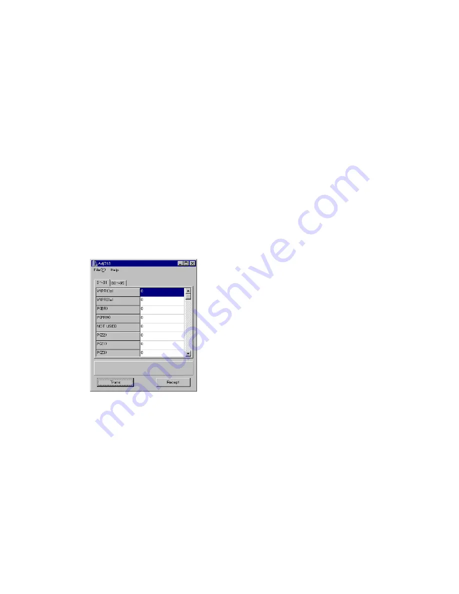
(3) Activate the ADJ program (ADJ713.EXE).
At this point, adjustment data of each item is set as 0 (zero).
Summary of Contents for QV-8000SX
Page 1: ...R QV 8000SX OCT 1999 without price KX 714 Ver 2 Dec 1999 ...
Page 38: ... 36 63 All parts separated 62 Remove DP panel 61 Unhook DP panel from behind and push it out ...
Page 45: ... 43 C PCB PCB K714D C PRINTED CIRCUIT BOARDS ...
Page 46: ... 44 D PCB PCB K714D D ...
Page 47: ... 45 L PCB PCB K714D L ...
Page 48: ... 46 MD PCB PCB K714D MD ST PCB PCB K714D ST ...
Page 49: ... 47 SCHEMATIC DIAGRAMS C PCB PCB K714D C CIRCUIT ...
Page 50: ... 48 D PCB PCB K714D C CIRCUIT ...
Page 51: ... 49 L PCB PCB K714D C CIRCUIT ...
Page 52: ... 50 MD PCB PCB K714D C CIRCUIT ...
Page 53: ... 51 ST PCB PCB K714D C CIRCUIT ...


