background image

No

Operation

Display

Inspection contents

— 42 —

1

2

3

4

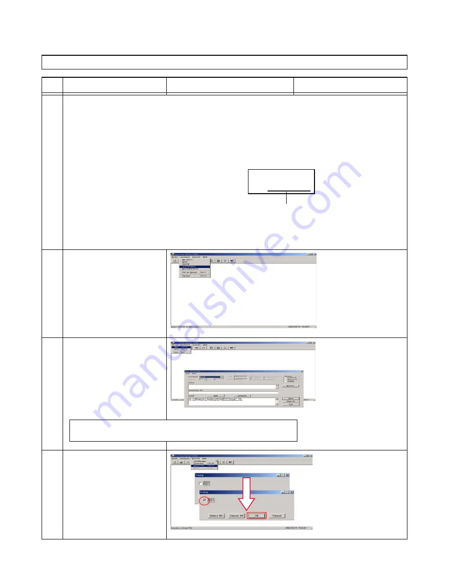
No.14 Wireless LAN (NOTE: This test is for DT-X5M10R only.)

= Preparation =
[Network setting of the computer]

[Access Point setting]

IP Address:

192.168.0.1

IP Address:

192.168.0.7

Subnet Mask: 255.255.255.0

Subnet Mask:

255.255.255.0

SS-ID:

Overseas

Radio Channel: 1

[LMWIN Utility software]
1. Edit “device.ini” in the Lmwin installed folder.
2. Add the IP Address used for DT-X5 to the file.

Address added to "device.ini"

(an address to be set for DT-X5)

[Operation of the Computer]

1. Start "Lmwin".
2. Choose “TCP/IP(NEW)” in

the Configure menu.

[Operation of the Computer]

1. Choose "New" in the Script

menu.

2. Make a script that performs

the communication with a
computer and DT-X5.

Sample Script:

[USE_IP]
1=192.168.0.15

  /S "C:\Program Files\lmwin\Send\xxxx.exe" C:\
  /R C:\xxxx.exe "C:\Program Files\lmwin\Receive\"

[Operation of the Computer]

1. Choose "Script file" in the

Execute menu.

2. Check "001" in the Dialog

Box.

3. Press "OK" button.

Summary of Contents for DT-X5M10E

Page 1: ...SERVICE MANUAL DT X5M10E M10R PX 791EE 791ME JUN 2004 HANDHELD TERMINAL Ver 1 Nov 2004 ...

Page 2: ...her company names and product names used in this document are trademarks or registered trademarks of their respective owners Important The company reserves the right to revise this publication or to change its contents without notice Information contained herein is for reference only and does not constitute a commitment on the part of the manufacturer or any subsequent vendor They assume no respon...

Page 3: ...perating time becomes extremely shorter even if it is fully charged 8Memory RAM can be backed up for about three days even without a main battery when a backup battery is fully charged 9It takes four days for a backup battery to become fully charged when a main battery is loaded 0Charging the DT X5 without loading the rechargeable battery pack will also light the charge LED Make sure to load the r...

Page 4: ...1EE Laser Scanner DT X5M10R O O O None PX 791ME Laser Scanner IEEE 802 11b Product Descriptions HA A61IO Bridge Satellite Cradle RS 232C USB for PC Connection RS 422 for daisy chain of multiple HA A60IO connec tion HA A60IO Bridge Basic Cradle USB for PC Connection HA A30CHG Cradle type Battery Charger HA A34AT Battery Charger Car Mount Unit ...

Page 5: ... 5A DT 5025LBAT Large capacity Battery Pack 3 7V 3 400mAh DT 5022CHG Dual Battery Charger MPC 577ADP AC Adapter for DT 5022CHG INPUT 100V 240V AC 50 60Hz OUTPUT 16V DC 2 8A DT 888RSC RS 422 Modular Cable for connecting Bridge Satellite Cradles DT 380USB USB Cable for connecting PC and Bridge Satellote Cradle DT 887AXA RS 232C Cross Cable for connecting PC and Bridge Satellite Cradle ...

Page 6: ...tion Ver 1 1 Range 1 Approx 5m Output 3dBm max Power Class 2 Wireless LAN Protocol none Complies with IEEE 802 11b Radio Frequency none 2 400 2 497 GHz Data Rate none 11Mbps max Range 2 none Indoor 50m Outdoor 150m Number of channels none Depends on Country Code Other functions none Multiple access point roaming Power Main Battery HA A20BAT battery pack HA A20BAT battery pack Requirement DT 5025LB...

Page 7: ...battery is loaded in the DT X5 at a normal temperature 9 0 to 40 C when the cradle is connected 10 Excluding the protrusion 11 When a standard battery pack is loaded excluding a strap 2 4 Consumable MODEL DT X5M10E DT X5M10R Power Charge Time Main Battery 7 Requirement HA A20BAT Approx 5 hours DT 5025LBAT Approx 10 hours Backup Battery 8 4 days Power Cunsumptioon DC 1 1A 3 5V DC 1 4A 3 7 5V Operat...

Page 8: ...s disassembly procedure The amount of screws you should be left with will be listed here also A box with a contains warnings An example of these types of boxes are shown below NOTE All disassembly procedures assume that the system is turned OFF and disconnected from any power supply the battery is removed too Maintenance Tools The following tools are recommended when working on the Handheld Termin...

Page 9: ...f and detach any power supplies When you want to unplug any cable wire be sure to disconnect it by the plug head Do not pull on the wire 6 Peripherals Turn off and detach any peripherals 7 Beware of static discharge ICs such as the CPU and main support chips are vulnerable to static electricity Before handling any part in the terminal discharge any static electricity inside the terminal When handl...

Page 10: ...ard 1 Remove the battery holder battery pack page 9 2 Separate the front and back case covers page 10 3 Remove the 1D Laser page 12 4 Remove the mainboard page 13 To Separate the Middle Case from the Front Case 1 Remove the battery holder battery pack page 9 2 Separate the front and back case covers page 10 3 Remove the 1D Laser page 12 4 Remove the mainboard page 13 5 Separate the middle case and...

Page 11: ...Terminal to the FREE position 3 Remove the battery cover 4 Remove any alkaline batteries if they are installed 5 Remove the alkaline battery holder or battery pack by pushing the tab 7 on the frame of the holder and pulling the battery pack removal tape 8 upwards Figure 2 1 Removing the Alkaline Battery Holder 3 Battery Cover 4 Alkaline Batteries 5 Battery Holder 6 Battery Pack 3 4 5 6 ...

Page 12: ...2 Remove screws 1 6 from the back of the case 3 Carefully a ribbon cable is still attached separate the front and back case assemblies 4 Release the ribbon cable 9 from the back case assembly Figure 2 2 Separating the Front and back Case Covers 7 Front Case Assembly 8 Back Case Assembly 6 Screws 7 8 ...

Page 13: ...parate the front and rear case assemblies see page 10 2 Remove screws 1 2 and release cables 3 5 from their locking collars 3 Lift the bridge board audio board and buzzer cover off the back case Figure 2 3 Removing the Bridge Board 6 Bridge Board 7 Audio Board 8 Buzzer Cover 2 Screws 7 8 6 ...

Page 14: ...y pack see page 9 and separate the front and rear case assemblies see page 10 2 Remove screws 1 2 and release cable 3 from its locking collar 3 Lift the 1D laser assembly off the front case assembly Figure 2 4 Removing the 1D Laser 4 1D Laser Assembly 2 Screws 4 ...

Page 15: ...ear case assemblies see page 10 and remove the 1D laser assembly see page 12 2 Remove screws 1 4 from the mainboard 3 Carefully ease up the mainboard and release cables 5 6 from their locking collars 4 Lift the mainboard off the front case assembly Figure 2 5 Removing the Mainboard 7 Mainboard 4 Screws 7 ...

Page 16: ... front and rear case assemblies see page 10 remove the 1D laser assembly see page 12 and remove the mainboard see page 13 2 Remove screws 1 2 3 Apply pressure at points 3 4 to ease the middle case out of the front case Figure 2 6 Separating the Middle Case from the Front Case 5 Front Case 6 Middle Case 2 Screws 6 5 ...

Page 17: ...e front and rear case assemblies see page 10 remove the 1D laser assembly see page 12 remove the mainboard see page 13 and separate the middle case from the front case see page 14 2 Carefully ease the key pad out of the front case Figure 2 7 Removing the Key Pad 1 Key Pad 2 Front Case 2 1 ...

Page 18: ...se assemblies see page 10 remove the 1D laser assembly see page 12 remove the mainboard see page 13 and separate the middle case from the front case see page 14 2 Carefully ease there may be some tapes attached to the LCD the LCD out of the middle case Figure 2 8 Removing the LCD 1 LCD 2 Middle Case 2 1 ...

Page 19: ...the Program Visit the following websites Service CD ROM for CASIO distributors Casio Technical Support Web site http www casio co jp English system Microsoft Web site http www microsoft com If you are testing the Wireless functions you will nedd a Wireless LAN access point Setup Programs Your computer running the Windows XP operating system should be up and running The following programs can then ...

Page 20: ...xtracted LMWIN Utility Software 2 Extract all the files from the zipped file Lmwin601 full zip to a folder e g create a folder named Lmwin601 full on the desktop 3 Execute IRXpressUSBIrDA exe and install the USB driver for HA A60IO HA A61IO IRXpressUSBIrDA exe is contained in the following folder Lmwin601 full Driver USB Lmwin601 full is the folder into which the zipped file in the above step 2 is...

Page 21: ...sk bar 2 Place the DT X5 on the HA A60IO HA A61IO 3 Execute AciveSync by DT X5 Top Menu 1 Programs 2 Settings 3 Task Manager 4 Tray Icon Manager 5 Application Loader 6 Version Info Communication 1 Bluetooth 2 FLCE 3 ActiveSync 4 Ping ActiveSync 5 Ping Tool 6 IP config Programs1 Programs 1 Mail 2 Browser 3 Communication 4 Utility 5 User Application Choose 1 Programs Choose 3 Activesync Choose 3 Com...

Page 22: ...e and browse to FlashDisk 7 Copy all the programs from the test directory to the FlashDisk directory Figure Copy Test Programs to Flash Disk 4 2 Booting and Ending the Hardware Diagnostic Program To boot the program 1 Press the power button 2 Push 0 key which is an undisclosed com mand Power Button Top Menu 1 Programs 2 Settings 3 Task Manager 4 Tray Icon Manager 5 Application Loader 6 Version Inf...

Page 23: ...y while FlashDisk is selected highlighted in black Next push R key 6 Push ENT key while 1 exe is selected highlighted in black The symbol on the lower right corner changes from 1 to F when Fn key is pressed Make sure to push R key after confirming this The hardware diagnostic program is booted The content of the FlashDisk is displayed FlashDisk 1 4 1 exe Backlight exe Burnlne exe Buzzer exe CliWLA...

Page 24: ... Test Programs MAKE SURE YOU DELETE THE TEST PROGRAMS FROM THE TERMINAL AFTER FINISHING THE TEST PROCESS 1 Return to the Top Menu and press the 0 key 2 Enter the password and press Enter The default password is 12346789 3 Choose FlashDisk Format from the System menu by pressing the 1 key 4 Choose Format from the FDISK Format menu by pressing the 1 key 5 Choose Yes from the format warning menu by p...

Page 25: ...37 12 RTC O O P 38 13 Bluetooth O O Computer with Bluetooth Module P 39 14 Wireless LAN O Computer Access point P 42 4 4 Function Test Inspection Item Table Composition Diagram for Testing 1 The status of IrDA inspection is to be OK if the hardware diagnostic program can be copied refer to page 19 Test object DT X5 HA A60IO Bridge Basic Cradle USB cable LAN cable Computer with Bluetooth module AD ...

Page 26: ...d data OK Check data OK CLR Exit Back to Main Menu Push CLR key Confirm the display on the left PSRAM Test 1 Write Read Compare 2 Memory Backup test PSRAM Test 1 Write Read Compare 2 Memory Backup test TestMenu V0 22F 1 1 Factory Test 2 PSRAM Test 3 ROM Test 4 NAND Test 5 Buzzer Test 6 Vibrator Test 7 LED Test 8 Key Button Test 9 Next Page PSRAM test is automatically executed Confirm the display o...

Page 27: ...Sum2 yyyyyyyy CLR Exit Display Test Menu 1 Select 3 ROM Test No 3 ROM TestMenu V0 22F 1 1 Factory Test 2 PSRAM Test 3 ROM Test 4 NAND Test 5 Buzzer Test 6 Vibrator Test 7 LED Test 8 Key Button Test 9 Next Page The Check Sum value of ROM is displayed The measured value should be Sum1 Sum2 When OS is ver xxxx ...

Page 28: ...Back to Main Menu Push CLR key NAND Test Write data OK Read data OK Check data OK CLR Exit TestMenu V0 22F 1 1 Factory Test 2 PSRAM Test 3 ROM Test 4 NAND Test 5 Buzzer Test 6 Vibrator Test 7 LED Test 8 Key Button Test 9 Next Page Flash Disk test is automatically executed Confirm the display on the left ...

Page 29: ... Test 1 Frequency Test 2 Freq Up Down 3 Freq loop Test 4 Volume Test Select 1 Frequency Test Confirm that the buzzer sounds in the order of 512Hz 2048Hz and 8192Hz 1 2 3 Confirm the display on the left after the buzzer stops Buzzer Test 1 Frequency Test 2 Freq Up Down 3 Freq loop Test 4 Volume Test Buzzer Test Freq 512 2048 8192Hz CLR Exit ...

Page 30: ...r Test Freq 2731Hz Volume Min Mid Max CLR Exit Back to Main Menu TestMenu V0 22F 1 1 Factory Test 2 PSRAM Test 3 ROM Test 4 NAND Test 5 Buzzer Test 6 Vibrator Test 7 LED Test 8 Key Button Test 9 Next Page Buzzer Test 1 Frequency Test 2 Freq Up Down 3 Freq loop Test 4 Volume Test Confirm the buzzer volume changes Min Mid Max Push CLR key ...

Page 31: ...stMenu V0 22F 1 1 Factory Test 2 PSRAM Test 3 ROM Test 4 NAND Test 5 Buzzer Test 6 Vibrator Test 7 LED Test 8 Key Button Test 9 Next Page Confirm the display on the left Vibrator Test 1 ON OFF 2 On Off Loop Buzzer Test Vibrator On Off test CLR Exit Vibrator Test 1 ON OFF 2 On Off Loop Confirm that DT X5 vibrates Confirm the display on the left after a while ...

Page 32: ... V0 22F 1 1 Factory Test 2 PSRAM Test 3 ROM Test 4 NAND Test 5 Buzzer Test 6 Vibrator Test 7 LED Test 8 Key Button Test 9 Next Page Confirm the display on the left LED Test 1 LED Test LED Test Lighting Red Green Orange CLR Exi LED Test 1 LED Test Confirm that the two LEDs changes Red Green Orange Confirm the display on the left after the LED is turned off ...

Page 33: ... 6 V R 7 Down 8 Fn 9 0 CLR 1 V 0 2 F8 Exit Enter F1 F2 V F3 F4 F5 F6 F7 F8 F8 Exit TestMenu V0 22F 1 1 Factory Test 2 PSRAM Test 3 ROM Test 4 NAND Test 5 Buzzer Test 6 Vibrator Test 7 LED Test 8 Key Button Test 9 Next Page Menu is displayed after all the keys are inputted Confirm that V is displayed for the inputted key Confirm the display on the left After inputting all the above keys input any o...

Page 34: ...ct 1 Backlight Test Confirm the display on the left Push CLR key Back Light Test CLR Exit Confirm the display on the left nothing displayed Select 4 LCD Step by step Confirm the display on the left Display Test 1 Backlight Test 2 Backlight shading 3 LCD Test 4 LCD Step by step Display Test 1 Backlight Test 2 Backlight shading 3 LCD Test 4 LCD Step by step ...

Page 35: ...h Left Trigger key Confirm the display on the left black Confirm the display on the left nothing displayed Push Left Trigger key Confirm the display on the left gray Push Left Trigger key Confirm the display on the left vertical stripes Push Left Trigger key 5 6 7 8 ...

Page 36: ...gger key Confirm the display on the left inverse check highlighted 9 10 11 12 13 Push Left Trigger key Confirm the display on the left Back to Main Menu Push CLR key TestMenu V0 22F 2 1 Display Test 2 Infrared Ray Test 3 Bluetooth Test 4 Laser Test 5 Wireless LAN Test 6 Sensor Test 7 Serial Port Test 8 Previous Page 9 Next Page Display Test 1 Backlight Test 2 Backlight shading 3 LCD Test 4 LCD Ste...

Page 37: ...Confirm the display on the left Select 1 ScanRead Laser Test 1 ScanRead 2 ScanRead 1000 3 ScanRead Loop CLR Exit Confirm whether the displayed data is correct Read the test barcode by pushing Trigger key Confirm the display on the left Laser Test 1 Scan bar code 2 Auto Scan 1000 times 3 Loop Test Scan Test Data LTR Scan ENT Exit Scan Test 1234567890123 LTR Scan ENT Exit ...

Page 38: ... the left Push CLR key Laser Test 1 ScanRead 2 ScanRead 1000 3 ScanRead Loop CLR Exit Back to Main Menu Push CLR key TestMenu V0 22F 2 1 Display Test 2 Infrared Ray Test 3 Bluetooth Test 4 Laser Test 5 Wireless LAN Test 6 Sensor Test 7 Serial Port Test 8 Previous Page 9 Next Page Laser Test 1 Scan bar code 2 Auto Scan 1000 times 3 Loop Test ...

Page 39: ...Ambient temperature approx 5 to 10 ºC Select 1 Sensor Test Confirm the display on the left Push CLR key Sensor Test Cradle Offline BatVol 3954mV BatType LION Temperature 27 ºC CLR Exit Back to Main Menu Push CLR key Confirm the display on the left Sensor Test 1 Sensor Test Sensor Test 1 Sensor Test TestMenu V0 22F 2 1 Display Test 2 Infrared Ray Test 3 Bluetooth Test 4 Laser Test 5 Wireless LAN Te...

Page 40: ...enu RTC Display Date 2004 03 31 Time 23 48 15 CLR Exit Display Test Menu 3 Select 4 RTC Confirm that the date is displayed and the clock operates No 12 RTC TestMenu V0 22F 3 1 Burn In Test 2 WLAN Country Code 3 Serial ID Set 4 RTC 5 OBR Set 6 Memory Test 7 Previous Page 8 Exit ...

Page 41: ...etooth 2 FLCE 3 ActiveSync 4 LAN ActiveSync 5 Ping Tool 6 IP config Bluetooth Tool 1 Power ON 2 Device List 3 Device Inquiry 4 Settings 5 Connection Device Inqiry BT Device was found 1 devices ENT CLOSE Select 3 Communication Confirm the display on the left Select 1 Bluetooth Select 3 Device Inquiry Bluetooth is initialized The display is as shown on the left after initialization Bluetooth devices...

Page 42: ...ASIO PC Push ENT key Select 4 Transmission Confirm the display on the left xxxxx 1 Properties 2 Services 3 Bonding 4 Transmission 5 Register Device Confirm the display on the left Confirm the display on the left File Transmission 1 Select File Name 2 Input File Name Select 1 Select File Name File Open 1 1 Flash DIsk My Documents Network profiles Program Files Release Temp Windows ...

Page 43: ...evice shows a message that it received a Connection Request accepts the connection request File transfer starts Confirm the display on the left The display is as shown on the left after the file transfer Push ENT key Connected device Confirms whether the file has been normally received File Transmission aaa exe Transmission was completed ENT CLOSE xxxxx 1 Properties 2 Services 3 Bonding 4 Transmis...

Page 44: ...ed folder 2 Add the IP Address used for DT X5 to the file Address added to device ini an address to be set for DT X5 Operation of the Computer 1 Start Lmwin 2 Choose TCP IP NEW in the Configure menu Operation of the Computer 1 Choose New in the Script menu 2 Make a script that performs the communication with a computer and DT X5 Sample Script USE_IP 1 192 168 0 15 S C Program Files lmwin Send xxxx...

Page 45: ...e display on the left Settings 1 2 1 Scanner 2 Contrast Bright 3 Power 4 Memory 5 PC Connection 6 WLAN Settings 7 Network Dial Up 8 Password 9 Buzzer Operation of the DT X5 Select 6 WLAN Settings Operation of the DT X5 Select 1 Power Select 1 Power ON Confirm the display on the left WLAN Settings 1 Power OFF 2 WLAN Tool WLAN Settings 1 Power ON 2 WLAN Tool DT X5 is now ready for wireless communica...

Page 46: ...y Select 1 OK Operation of the DT X5 Select 4 Connection Net IP Address 1 Use DHCP ON 2 IP address 3 Subnet mask 4 Default gateway IP Address 1 Use DHCP OFF 2 IP address 192 168 0 15 3 Subnet mask 255 255 255 0 4 Default gateway Config 1 IP address 2 Name Server 3 Network config on 4 Connectable Net 5 Preferred Net 6 Network type net 7 Preferred only on 8 Power Save on Connectable net 1 Renew 2 Ov...

Page 47: ...ms 3 Communication 2 FLCE 2 Rewrite the parameter Y LAN 192 168 0 1 M 3 Input Fn and 9 keys Confirm the display on the left Confirm that the antenna icon is displayed on the task bar If the icon is not displayed perform a reset Confirm the display on the left Communication starts The display is as shown on the left when the communication ends normally Communication 1 Bluetooth 2 FLCE 3 ActiveSync ...

Page 48: ...fter about 1 second Push ENT key When an error occurs Confirm the display on the left OBR Setting Ver1 00 1 OBR Calib SET Setting Status Setting NG 9 EXIT OBR Setting Ver1 00 Setting Finished Setting OK 1 SET 2 Retry 9 CANCEL OBR Setting Ver1 00 Setting Finished Setting OK 1 SET 2 Retry 9 CANCEL 4 5 OBR CalibrationSetting Perform the OBR Calibration Setting after replacing the following Laser modu...

Page 49: ...Select 9 EXIT OBR Setting Ver1 00 1 OBR Calib SET Setting Status Setting OK 2 Retry 9 EXIT Confirm the display on the left Back to Main Menu Test Menu VO 22F 3 1 Burn In Test 2 WLAN Country Code 3 Serial ID Set 4 RTC 5 OBR Set 6 Memory Test 7 Previous Page 8 Exit ...

Page 50: ...1 1 SET 2 Retry 9 Cancel Confirm the display on the left Confirm whether the inputted number is correct Confirm the display on the left Back to Main Menu Confirm the display on the left Input the serial number of the product Push ENT key Select 1 Serial ID SET Select 1 SET Select 9 EXIT Test Menu VO 22F 3 1 Burn In Test 2 WLAN Country Code 3 Serial ID Set 4 RTC 5 OBR Set 6 Memory Test 7 Previous P...

Page 51: ...3 Push CLR key Push ENT key Back to Main Menu Confirm the display on the left The Status box is displayed Confirm whether the country code has bee set correctly Japan 04 Europe 02 America 01 Test Menu V0 22F 3 1 Burn In Test 2 WLAN Country Code 3 Serial ID Set 4 RTC 5 OBR Set 6 Memory Test 7 Previous Page 8 Exit WLAN Country Code 1 Japan 04 2 Europe 02 3 America 01 4 Country Code Check WLAN Countr...

Page 52: ...he country code has bee set correctly Japan 04 Europe 02 America 01 Select 4 Country Code Check Test Menu V0 22F 3 1 Burn In Test 2 WLAN Country Code 3 Serial ID Set 4 RTC 5 OBR Set 6 Memory Test 7 Previous Page 8 Exit WLAN Country Code 1 Japan 04 2 Europe 02 3 America 01 4 Country Code Check WLAN Country Code 1 Japan 04 2 Europe 02 3 America 01 4 Country Code Check Status OK X Program OK Country ...

Page 53: ...chematic diagram PCB Name Description System Block Diagram P 52 MAIN PCB DC DC Charger 1 10 P 53 DC DC VDET 2 10 P 54 CPU 3 10 P 55 ASIC 4 10 P 56 Memory 5 10 P 57 Bluetooth 6 10 P 58 WLAN 7 10 P 59 LCD 8 10 P 60 Scanner 9 10 P 61 Keyboard Connector 10 10 P 62 BRIDGE PCB Connector 1 2 P 63 Backup Battery 2 2 P 64 Key FPC Keyboard P 65 IRDA P 66 Trigger P 66 Buzzer P 66 Page ...

Page 54: ...MMU TLB INTC RTC X32k X48M X32k PSRAM NOR Flash ROM X27 648M Thermistor Maintenance Port BTIF Bluetooth Module Laser Scanner BSC PBS DMAC TPIF TCM ASIC INTC RCS PSC RTC LCDC LCD Antenna LSC ISC I2CM NLC NSC NVC IRIF CBC CPC KPC LED BUZZER VIBRATOR IrDA Wireless LAN 5 Key KBC 23 Key Li ION Sub BATT LR6 2 USB POWER SUPPLY UNIT SCIF ...

Page 55: ... 0 1u R278 10 1 4W R102 91 0 25W 1206 D33 RB521S 30 Q51 RHU002 TP11 TP C10 33p U34 74AHC1G14 R104 54 9_1 Q1 SI1413EDH_SC70 D22 RB160M 30 Q55 RHU002 R11 10K SW1 ALPS_SPPB530600 R200 3K_1 C16 0 1u C115 100p C278 0 1u TP97 TP R277 3K_1 D3 V5 5MLA0402WH C6 470p TP13 TP R268 45 3K_1 C3 0 1u SYSPWREN 3 5 BATCVR 5 CHGFLTX CHGFLTX 5 LOVLT2LTM 3 5 LOVT4 3 CHGFLT 4 DMYEN 5 CHGEXEX SYSCLKEN 5 ALKDCTX 5 CHGEX...

Page 56: ...NGND BLGND L17 0 0805 R29 1M R227 1M Q39 SI1413EDH_SC70 3 2 4 5 6 1 U6 R1111 2 9 1 3 5 2 4 VDD CE OUT GND NC C26 10u 6 3V 0805 H6 R37 1M C264 0 01u R297 OPEN U7 R1111 1 8 1 3 5 2 4 VDD CE OUT GND NC PGND PGND U15 XC61CN1502MR SOT23 I G O VIN GND OUT PGND R230 100K_1 Q16 SI1413EDH_SC70 3 2 4 5 6 1 PGND LOVLT2LTM 2 5 C202 100p LOVT4 2 C220 0 01u 1 2 R34 178K_1 Q11 RHU002 G D S C265 0 01u C23 0 1u Fo...

Page 57: ...DACK0 PTE0 DACK1 PTE1 IRQ5 PTE2 TEND0 PTE3 TxD0 SCPT0 IrTx RxD0 SCPT0 SCK0 SCPT1 PTE7 TCLK PTE6 TxD2 SCPT2 RxD2 SCPT2 CTS2 SCPT5 RTS2 SCPT4 SCK2 SCPT3 NMI CA IRQ0 IRL0 PTH0 IRQ1 IRL1 PTH1 IRQ2 IRL2 PTH2 IRQ3 IRL3 PTH3 IRQ4 PTH4 RESETM RESETP TRST CKIO STATUS0 PTE4 RTS0 STATUS1 PTE5 CTS0 V29 1 2 V29 V33 1 2 3 4 5 6 7 8 1 2 3 4 5 6 7 8 V29 1 2 3 4 5 6 7 8 1 2 3 4 5 6 7 8 V33 V29 1 2 3 4 5 6 7 8 1 2 ...

Page 58: ...CAN0 TSTSCAN1 TSTBIST TSTBUS TSTUESR0 TSTUSER1 CRDLDCT ALKDCT ALKDRCTEN VD1Q1 VD1Q2 VD1Q3 VD1Q4 VD1Q5 VD1Q6 VD1Q7 VD1Q8 VD1Q9 VD1Q10 VD1Q11 VD1Q12 VD1Q13 VD1Q14 VD1Q15 VD1Q16 VD1Q17 GND27 VD2Q1 VD2Q2 VD2Q3 VD2Q5 VD2Q6 VD2Q7 VD2Q8 VD2Q9 VD2Q4 GND1 GND2 GND3 GND4 GND5 GND6 GND7 GND8 GND9 GND10 GND11 GND12 GND13 GND14 GND15 GND16 GND17 GND18 GND19 GND21 GND22 GND23 GND24 GND25 GND26 GND20 VD2Q10 ISLE...

Page 59: ...5 A16 A17 A18 A19 A20 A21 I O0 I O1 I O2 I O3 I O4 I O5 I O6 I O7 I O8 I O9 I O10 I O11 I O12 I O13 I O14 I O15 NC9 NC10 NC11 NC12 NC13 NC14 NC16 NC17 NC18 NC21 NC23 NC24 NC25 NC26 NC27 NC28 NC29 NC30 NC31 NC32 NC33 NC34 NC2 NC3 NC4 NC5 NC6 NC7 NC8 OE WE CEf1 CEf2 RY BY RESET WP ACC NC1 Vss2 Vss1 Vccf VccQf Vccm VCCS1 CEm LB UB MODE VCCS2 IC CE1S CE2S NC35 NC36 NC37 NC38 A17 D6 A18 A11 NA_RE 4 D7 ...

Page 60: ...PEN BLGND Q34 RHU002 G D S BTCTS 5 C190 100p C78 0 1u C217 OPEN BLGND BLGND BLGND R245 10K V30BT E1 RFANT5220110A0T U20 LBMA49BAE3 031 32 13 15 12 11 1 3 5 14 31 33 4 10 2 6 7 8 9 20 21 17 16 18 19 22 23 24 25 26 27 28 29 30 34 ANT TxD RxD RTS CTS GND1 GND2 GND3 GND4 GND5 GND6 VCC RST VDD18 NC2 NC3 NC4 NC5 NC6 NC7 SYNC IN OUT CLK NC8 NC9 NC10 NC11 NC12 NC13 NC14 NC15 NC16 VCCVCO C113 1000p C275 2 ...

Page 61: ...5 CFD6 R203 1M V30W CFD1 CFD15 TP104 TP VCFENX 5 CFSTSCHG WLANGND CFD12 CFD4 R202 1M C219 100p CFD13 R131 330K V30W V33W R208 1K WLAN_STATUS 4 CFD3 CFA1 WLANGND CFD15 C207 10u 6 3V 0805 CFWEX 5 CFD 0 15 CFD14 CFD1 RP234 1M 8P4R OPEN 1 2 3 4 5 6 7 8 CFOEX 5 CFREGX 5 R266 0 RP92 1M 8P4R OPEN 1 2 3 4 5 6 7 8 CFD11 U32 WLAN6065EBC2 R17 P17 M17 L17 K17 J17 H17 G17 F17 E17 D17 C17 B17 N17 P1 N1 M1 L1 K1...

Page 62: ...0p LCD C276 0 01u LCD 0 7 5 J6 22FLH SM1 TB 1 2 3 4 5 6 7 8 9 10 11 12 13 14 15 16 17 18 19 20 21 22 VOUT NC1 VDD NC2 VSS1 D7 SI D6 SCL D5 D4 D3 D2 D1 D0 RD WR A0 VSS2 RES VSS3 CS1 BL BL V33S LCDBLDIM 5 close to J6 TP18 TP29 TP27 LCDA 5 R87 1M TP24 U24 TPS61042 3 5 8 6 2 4 7 1 VIN CTRL SW GND Rs FB OVP LED TP21 LCDCSX 5 TP15 C86 10u 6 3V 0805 TP19 TP17 LCDWRX 5 LCDBLENX 5 TP25 R85 330K TP20 LCD 0 ...

Page 63: ...1u LSLSREN 5 C90 10u 6 3V 0805 LSTMG 5 LSPWREN 5 V29 TP33 1D LASER R248 10K C91 10u 6 3V 0805 TP34 V33S R134 1M OPEN LSSGL 5 R133 1M TP30 D37 V5 5MLA0402WH 1 2 SE_STATUS 4 Q27 SI1413EDH_SC70 3 2 4 5 6 1 R219 1M J12 8FLH SM1 TB 1 2 3 4 5 6 7 8 VCC LASER ON POWER EN SIGNAL TIMING NC1 NC2 GND C92 0 1u R279 82 ...

Page 64: ... 7 8 KOX2 5 KIX3 5 Q46 SI1413EDH_SC70 3 2 4 5 6 1 PGND PGND C96 1000p TP87 ICDCTX 5 C178 1000p TP90 V33S RP88 1M 8P4R 1 2 3 4 5 6 7 8 KIX1 5 V33 TP59 TP81 TP75 TP58 TXD0 4 C179 1000p V33B RXD0 RP84 1M 8P4R 1 2 3 4 5 6 7 8 TP94 C197 0 1u TP83 TP92 PGND C199 0 1u TP80 TP55 KEYX0 5 TP93 TP82 R224 100K TP70 TP79 V33 R136 100K BZCLK0 5 C97 1000p R137 100K TP64 TP60 SUB BOARD LOVLT3 3 5 C101 10u 6 3V 08...

Page 65: ... 2A PGND V33 TO IrDA B V29 PGND J3 BM02B SRSS TB 1 2 TO Maintenance Port VADP KEYX3 TP26 TP C1 10u 6 3V 0805 ICCSX 3 TP12 TP TP7 TP TP8 TP ICDRX 3 IRMODE TP14 TP SW1 ALPS_SKHMPUE010 1 2 3 4 ICDCTX V33B J6 BM04B SRSS TB 1 2 3 4 C8 0 1u TXD0T 3 IRTXD ICCSXT 3 Q2 RHU002 G D S TP3 TP C31 0 1u TP15 TP TXD0 3 TP19 TP IRMODE TP17 TP RXD0T 3 C4 0 1u MEMTE Q3 RHU002 G D S TP22 TP RAMPWRENX PGND J1 32FLH SM...

Page 66: ...VLT3 1 PGND PGND L4 LQH32CN100K23L R22 10K BT1 MAXELL_ML2032 T6 C32 4 7p OPEN PGND V33S D3 RB521S 30 A C R20 1M_1 PGND PGND R93 1M U3 LT1615ES5 1 5 4 1 3 2 VIN SHDN SW VFB GND Q9 RHU002 G D S VSUB Q6 RHU002 G D S PGND PGND R21 604K_1 PGND U5 ELM9724CBA SOT23 I G O VIN GND OUT RAMPWRENX 1 V33B D2 RB521S 30 A C LOVLTSUB 1 C20 0 1u R94 1M PGND R12 1K TP27 TP ...

Page 67: ...d 5 KOX0 KEYX2 3 KIX2 6 F2 CLR KOX2 ENTER KOX1 F6 PWRKEYX KIX1 POWER ON J1 1 2 3 4 5 6 7 8 9 10 11 12 13 14 15 16 17 18 F3 KOX3 9 KIX0 7 KEYX1 F1 DOWN KIX3 1 F8 2 F5 R ACTION F4 KOX4 L UP J2 CN1 1 F7 KOX5 FUNC 0 4 8 KEYX0 J3 CN1 1 Key FPC ...

Page 68: ...4 smd118x110 H3 smd118x110 PGND J2 CN1 1 C2 0 1u 1 2 U1 TFDU6102E 1 2 3 4 5 6 7 8 IRED Anode IRED Cathode Txd Rxd SD Mode Vcc Mode GND IRRXD D2 V5 5MLA0402WH 1 2 J3 CN1 1 L1 BEAD120 0805 V33IR VADP R1 10 0603 1 2 C1 10u 6 3V 0805 Trigger L J5 1 2 3 4 KEYX4 Trigger R KEYX3 J1 CN1 1 LS1 MQT 03EX 1 2 J2 CN1 1 D35 V5 5MLA0402WH 1 2 IRDA Supply FPC Trigger Trigger FPC Buzzer ...

Page 69: ... 67 6 EXPLODED VIEW FRONT CASE ASSY 3 1 7 4 2 5 6 ...

Page 70: ... 68 MIDDLE CASE ASSY 9 8 11 12 See LCD BLOCK DT X5M10R only See LASER BLOCK 14 13 15 10 14 ...

Page 71: ... 69 16 1 16 2 16 3 16 4 16 4 16 3 16 5 16 9 16 8 16 7 16 6 27 26 33 28 29 30 23 22 21 18 17 19 24 33 25 20 16 10 16 11 16 10 21 1 31 16 32 34 BACK CASE ASSY ...

Page 72: ... 70 LCD BLOCK 43 42 41 38 39 40 36 37 35 LASER BLOCK ...

Page 73: ...746 KEY PAD ASSY 42 W7917 101 1 1 CM A 7 1017 4742 VIBRATOR 25 90000 000 1 1 AU C MIDDLE CASE BLOCK M10E M10R 8 1017 4749 CASE MIDDLE 39 W7913 01A 1 1 BF X 9 1017 4748 FPC KEYBOARD 43 W7917 014 1 1 BQ C 10 1017 4755 ANTENNA WLAN 23 742R4 008 1 BW C 11 1017 4750 SHEET BATTERY REMOVAL 47 W7913 021 1 1 AA X 1017 4752 SHEET US 47 W7913 041 1 AC 1017 4751 SHEET 47 W7913 011 1 AD 1017 8336 PCB ASSY MAIN...

Page 74: ...AF C 30 1017 4730 COVER LARGE BATTERY 42 W791M 201 1 1 AF C 31 1017 4732 SCREW M2 5 6L 35 01125 6R0 1 2 2 AA X 32 10174728 1017 4718 SCREW TAP T2 6L SCREW TAP T2 4L 35 01120 6RB 35 C1120 4R0 4 4 AA X 33 1017 4718 SCREW TAP T2 4L 35 C1120 4R0 3 3 AA X 1017 8338 LABEL RATING EE 45 W7913 050 1 AD 1017 8339 LABEL RATING ME 45 W7913 040 1 AD Item 16 CASE ASSY BACK contains the following Items 16 1 1017...

Page 75: ...M10R 38 1017 4758 HOLDER LASER 42 W7913 010 1 1 AD X 39 1015 0529 LASER ASSY VLM3800 1 1 DV A 40 1017 4759 CABLE FFC 43 W791L 010 1 1 AD B 41 1017 4760 GLASS MIRROR 47 W791L 010 1 1 AW X 42 1017 4761 SPONGE 47 W791L 020 1 1 AA X 43 1017 4757 SCREW M2 4L 35 01120 4R0 A 3 3 AA X TOOLS M10E M10R SPECIAL SCREW DRIVER D3LU0X88G 2 0X20 A screw driver for the special screws fixing the case Quantity Price...

Page 76: ...Overseas Service Division 6 2 Hon machi 1 Chome Shibuya ku Tokyo 151 8543 Japan Ver 1 Nov 2004 Correction of the PART LIST Deletion of the unavailable parts P72 Change of a part in ITEM NO 32 P72 Addition of the price code ...

Reviews: