background image

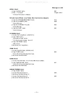
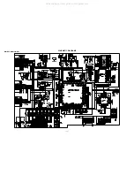
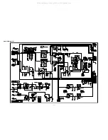
— 32 —

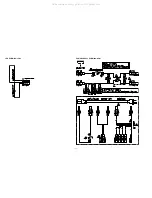
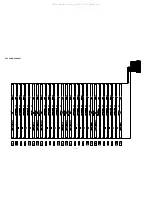
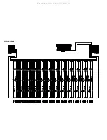
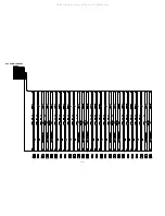
LED PCB M419-LCA2

POWER SUPPLY PCB M420-ACA1

All manuals and user guides at all-guides.com

Summary of Contents for Celviano AP-80R

Page 1: ...ELECTRONIC KEYBOARD AP 80R SEP 2004 AP 80R All manuals and user guides at all guides com a l l g u i d e s c o m ...

Page 2: ...ecifications 1 Block Diagram 3 Circuit Description 4 Printed Circuit Boards 6 Disassembly 10 Diagnostic Program 17 Exploded View 20 Parts List 22 Schematic Diagrams 26 All manuals and user guides at all guides com ...

Page 3: ...Tunes Piano Group 50 Song Group 30 10 loaded song data Approximately 132 kilo bytes Tempo 20 to 255 Demo Sequential looping of all 80 preset tunes Song Volume Adjustable Lesson Function Lesson Part Left hand right hand Song Memory Number of Songs Two 1 Song Recording 1 Free Recording Recorded Data Song Recording Right hand part left hand part both hand parts Free Recording Track 1 chord accompanim...

Page 4: ...ltage 10mV MIDI OUT IN USB port Speakers ø16 cm 2 ø5 cm 2 Output 20W 20W Power Supply AP 80R 120V AP 80RV 220 240V Power Consumption 60W Dimensions Digital Piano without stand 138 0 47 6 24 4 cm 54 3 8 18 3 4 9 5 8 inch Digital Piano 138 1 47 7 84 6 cm 54 7 16 18 13 16 33 5 16 inch Weight Digital Piano without stand approximately 41 6 kg 91 7 lbs Digital Piano Approximately 54 0 kg 119 0 lbs All m...

Page 5: ...3B NNTC 116 IC7 MAA1 PCB LED Button FI0 10 SI0 10 KC0 7 MA1 22 MD0 15 RAM 128K 16 Static RAM CY62136DV30LL55ZIT IC11 MAA1 PCB MA1 17 MD0 15 SP SP RESET MA1 MA21 23 MD7 15 MWEB MRDB DB4 7 CONT RS RW E MIDI IN OUT MOUT MIN SOFT SOSTENUTO DAMPER VBUS D D VA5 5V VA15 15V Power Supply IC2 4 Q7 8 D13 14 17 18 21 24 PS1 PCB L R LINE OUT PEDAL USB L R MIC MIC VR Filter NJM2068DD IC9 PS1 PCB VD3 3V RESET I...

Page 6: ... F21 F2 1 G21 G2 1 SI2 C2 2 D22 D2 2 E22 F22 F2 2 G22 G2 2 FI3 A21 A2 1 B21 C31 C3 1 D31 D3 1 E31 SI3 A22 A2 2 B22 C32 C3 2 D32 D3 2 E32 FI4 F31 F3 1 G31 G3 1 A31 A3 1 B31 C41 SI4 F32 F3 2 G32 G3 2 A32 A3 2 B32 C42 FI5 C4 1 D41 D4 1 E41 F41 F4 1 G41 G4 1 SI5 C4 2 D42 D4 2 E42 F42 F4 2 G42 G4 2 FI6 A41 A4 1 B41 C51 C5 1 D51 D5 1 E51 SI6 A42 A4 2 B42 C52 C5 2 D52 D5 2 E52 FI7 F51 F5 1 G51 G5 1 A51 A...

Page 7: ...ON 2 REGISTRATION SYNTH PAD BRASS SETTING LAYER STORE REGISTRATION 3 REGISTRATION GM TONES REED SC0 SC1 SC2 SC3 SC4 SC5 SC6 SI0 SI1 SI2 SI3 SI4 SI5 SI6 SI7 TEMPO 2 TEMPO 3 TEMPO 4 VARIOUS LATIN EUROPEAN SING ALONG ECHO POPS FINGERED FULL RANGE CHORD CASIO CHORD TEMPO 1 TRACK 1 L TRACK 2 R START STOP PLAY STOP REPERT LL0 LL1 LL2 LH25 LH24 LH23 LH22 LH21 LH20 LH19 LH18 JAZZ ROCK DANCE FUNK FOR PIANO...

Page 8: ... 6 PRINTED CIRCUIT BOARDS MAIN PCB M419 MAA1 All manuals and user guides at all guides com ...

Page 9: ... 7 SUB PCB M429 PS1 JACK PCB M429 PSA3 JACK PCB M429 PSA2 POWER LED PCB M429 PSA4 All manuals and user guides at all guides com ...

Page 10: ... CNA1 CONSOLE PCB M429 CNA2 CONSOLE PCB M429 CNA5 CONSOLE PCB M429 CNA3 CONSOLE PCB M429 CNA4 POWER SUPPLY PCB M420 ACA1 LED PCB M419 LCA1 LED PCB M419 LCB2 I O PCB M429 SMA1 All manuals and user guides at all guides com ...

Page 11: ... 9 KEY PCB MCPK KYA1 KYB2 KYA3 All manuals and user guides at all guides com a l l g u i d e s c o m ...

Page 12: ...SEMBLY 1 Remove eight screws on the back of the main unit and then remove the top board 2 Remove one screw and the key cover 3 Remove six screws and the wire netting All manuals and user guides at all guides com ...

Page 13: ...move six connectors on the main PCB 5 Remove eight screws and the main PCB To remove the panel part 6 Remove two connectors and six screws To remove the sub PCB M429 PS1 power PCB M420 ACA1 and the transformer 9 Remove seven connectors 10 Remove 14 screws sub PCB M429 PS1 power PCB M420 ACA1 and the transformer 7 Remove the panel part from the main unit 8 Remove two screws in the power switch and ...

Page 14: ...29 PS2 Note Arrange the cables using the Insulok tie when assembling 13 Remove the Insulok tie 14 Remove one connector two screws and the jack PCB M429 PS3 Note Arrange the cables using the Insulok tie when assembling To remove the speaker only on the right side 15 Remove six screws and two speakers All manuals and user guides at all guides com ...

Page 15: ...screws of the M429 CN2 PCB 18 Remove the volume knob of the M429 CN2 PCB To remove the console PCB M429 CN PCB ASSY 19 Remove four screws of the M429 CN3 PCB 20 Remove three screws of the M429 CN4 PCB 21 Remove the volume knob of the M429 CN4 PCB 22 Remove three screws of the M429 CN5 PCB 23 Remove the volume knob of the M429 CN5 PCB 24 Remove one connector and the M429 CN PCB ASSY Note How to fix...

Page 16: ... PCB M419 LCA1 25 Remove four screws of the M429 SMA1 PCB 26 Remove 16 screws and the LCD unit Note Fix the screws in the right order when assembling Precautions during assembly Arrange the cables around the panel part All manuals and user guides at all guides com a l l g u i d e s c o m ...

Page 17: ...ve seven screws on the bottom 28 Remove two screws and the M429 PSA4 PCB To remove the keyboard 29 Remove 16 screws on the bottom 30 Remove three screws on the surface 31 Separate the case and the keyboard All manuals and user guides at all guides com ...

Page 18: ...eys 1 The length of this one key is different 2 The number of pins on the upper side is different from that on the lower side 3 Fix the pins tightly 32 1 Pull the hammer and 2 Aremove the key from the hammer 33 Insert the edge of the tweezers as shown in a part of the figure and then remove the keys All manuals and user guides at all guides com ...

Page 19: ... 1 Press PIANO button AOK 2 ROM check 1 Press E PIANO CHROMATIC button OOK 3 SWITCH check 1 Press ORGAN button CCH 2 Press the buttons in the following order SWITCH No The Switch number appears on the LCD The button numbers are written in hexadecimal numerals 00 01 02 03 04 05 06 07 08 09 0A 0B 0C 0D 0E 0F 10 11 12 18 19 1A 1B 1C 1D 1E 1F 20 21 22 CCH 23 24 25 26 27 28 29 2A 2B 2C 2D 2E 2F 30 31 3...

Page 20: ...n Sound A4 sin wave sound The Tuning meter indicate A4 2 3 Press GM TONES button Stop sound 4 Disconnect the Tuning Meter 7 MIDI check 1 Connect the MIDI Cable MIDI IN OUT 2 Press POPS button DOK Sound C4 E4 and G4 polyphonic beep 3 Disconnect the MIDI Cable 8 USB check 1 Connect the USB Cable To a PC that USB driver installed 2 Press DANCE FUNC button ACT Sound C4 E4 and G4 polyphonic beep 3 Disc...

Page 21: ...check 1 Insert the SMART MEDIA CARD 16MB 2 Press VARIOUS button UOK All LEDs turn off Takes about 3 sec Sound C4 E4 and G4 polyphonic beep 3 Remove the SMART MEDIA CARD 12 PRODUCT NUMBER check 1 Press FOR PIANO button 429 Display shows model number 2 Press FOR PIANO button Display shows internal RON Version 3 Press FOR PIANO button Display shows external RON Version 13 DIAGNOSTIC PROGRAM IS FINISH...

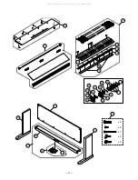
Page 22: ...EXPLODED VIEW 5 9 9 3 6 10 6 1 7 2 8 10 22 20 21 8 13 23 14 26 24 25 27 4 1 11 12 29 30 31 33 35 34 33 35 32 20 17 20 18 16 16 20 17 17 15 17 20 19 19 20 17 28 All manuals and user guides at all guides com ...

Page 23: ... 21 x4 x6 x1 x2 x2 59 62 61 64 63 65 60 45 51 52 53 40 50 47 48 49 43 46 44 56 55 54 58 57 39 37 36 38 66 41 42 All manuals and user guides at all guides com ...

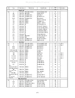
Page 24: ...ment if you need these parts for refurbish 1 Prices and specifications are subject to change with out prior notice 2 As for spare parts order and supply refer to the GUIDEBOOK for Spare parts Supply published seperately 3 The numbers in item column correspond to the same numbers in drawing PARTS LIST AP 80R All manuals and user guides at all guides com ...

Page 25: ...5 PCB ASSY PS1E TK RJM504708 001 1 CW B 240V CN17 35005845 CONNECTOR B3B PH K S 1 AA C CN20 35015551 CONNECTOR B8B PH K S 1 AA C D10 D5 D6 D9 10047403 DIODE 1N5401 EP 4 AA C D11 D12 D7 D8 10036785 DIODE 2A02B 4 AA C FU3 10052231 FUSE 51MS010L 1 AC B 120V FU3 10054029 FUSE 50T010H 1 AC B 240V FU1 FU2 10052230 FUSE 51MS040L 2 AC B 120V FU1 FU2 10054030 FUSE 50T040H 2 AC B 240V IC1 10043418 IC LM4765...

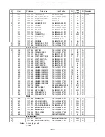
Page 26: ...RJM504663 001 1 CE C CONSOLE UNIT N 13 10174520 PLATE DISPLAY RJM504085 001V01 1 AD C N 14 10174877 PANEL ASSY TK RJM504665 001 1 CF C N 15 10174518 RUBBER KEY A RJM504079 001V01 1 AC X N 16 10174519 RUBBER KEY B RJM504080 001V01 2 AA X N 17 10172215 BUTTON TACT RJM504081 010V01 8 AC X N 18 10172216 BUTTON TACT RJM504081 011V01 1 AE X N 19 10172217 BUTTON TACT RJM504081 012V01 5 AG X N 20 10172218...

Page 27: ...01 1 AJ C 45 10135430 WHITE KEY SC RJM502796 001V01 1 AJ C 46 10135435 HAMMER ASSY W1 TK RJM503155 001 13 AL C 47 10135436 HAMMER ASSY W2 TK RJM503216 001 13 AL C 48 10135437 HAMMER ASSY W3 TK RJM503217 001 13 AL C 49 10135438 HAMMER ASSY W4 TK RJM503218 001 13 AL C 50 10135439 HAMMER ASSY B1 TK RJM503219 001 9 AK C 51 10135440 HAMMER ASSY B2 TK RJM503220 001 9 AK C 52 10135442 HAMMER ASSY B3 TK R...

Page 28: ... 26 SCHEMATIC DIAGRAMS MAIN PCB M419 MAA1 All manuals and user guides at all guides com ...

Page 29: ... 27 SUB PCB M429 PS1 All manuals and user guides at all guides com ...

Page 30: ... 28 CONSOLE PCB M429 CNA1 All manuals and user guides at all guides com ...

Page 31: ... 29 CONSOLE PCB M429 CNA2 All manuals and user guides at all guides com a l l g u i d e s c o m ...

Page 32: ... 30 CONSOLE PCBs M429 CNA3 CNA4 CNA5 M429 CNA3 M429 CNA4 M429 CNA5 All manuals and user guides at all guides com ...

Page 33: ... 31 LED PCB M419 LCA1 All manuals and user guides at all guides com ...

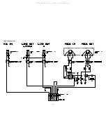
Page 34: ... 32 LED PCB M419 LCA2 POWER SUPPLY PCB M420 ACA1 All manuals and user guides at all guides com ...

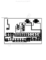
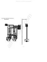
Page 35: ... 33 JACK PCB M429 PSA2 All manuals and user guides at all guides com ...

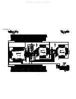
Page 36: ... 34 M429 PSA3 M429 PSA4 JACK PCB M429 PSA3 POWER LED PCB M429 PSA4 All manuals and user guides at all guides com a l l g u i d e s c o m ...

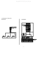
Page 37: ... 35 JACK PWB M420 PDA1 IO PCB M429 SMA1 M420 PDA1 M429 SMA1 All manuals and user guides at all guides com ...

Page 38: ... 36 KEY PCB MCPK KYA1 All manuals and user guides at all guides com ...

Page 39: ... 37 KEY PCB MCPK KYB2 All manuals and user guides at all guides com ...

Page 40: ... 38 KEY PCB MCPK KYA3 All manuals and user guides at all guides com ...

Page 41: ...CASIO TECHNO CO LTD Overseas Service Division 6 2 Hon machi 1 Chome Shibuya ku Tokyo 151 8543 Japan All manuals and user guides at all guides com a l l g u i d e s c o m ...

Reviews: