


— 16 —
1
2
a
7 pin
4 pin
1
2
2
8 pin
3 pin
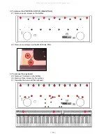
34. Remove eight rubber keys.
35. Remove 32 screws and the key PCB.
* Precautions when assembling the rubber keys
1
The length of this one key is different.
2
The number of pins on the upper side is different from that on the lower side.
3
Fix the pins tightly.
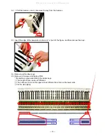
32.
1
Pull the hammer, and
2
Aremove the key from the hammer.
33. Insert the edge of the tweezers as shown in “a” part of the figure, and then remove the keys.
All manuals and user guides at all-guides.com
Summary of Contents for Celviano AP-80R
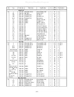
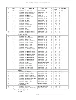
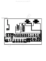
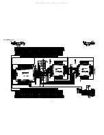
Page 8: ... 6 PRINTED CIRCUIT BOARDS MAIN PCB M419 MAA1 All manuals and user guides at all guides com ...
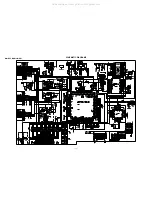
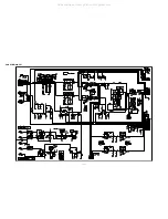
Page 28: ... 26 SCHEMATIC DIAGRAMS MAIN PCB M419 MAA1 All manuals and user guides at all guides com ...
Page 29: ... 27 SUB PCB M429 PS1 All manuals and user guides at all guides com ...
Page 30: ... 28 CONSOLE PCB M429 CNA1 All manuals and user guides at all guides com ...
Page 33: ... 31 LED PCB M419 LCA1 All manuals and user guides at all guides com ...
Page 35: ... 33 JACK PCB M429 PSA2 All manuals and user guides at all guides com ...
Page 38: ... 36 KEY PCB MCPK KYA1 All manuals and user guides at all guides com ...
Page 39: ... 37 KEY PCB MCPK KYB2 All manuals and user guides at all guides com ...
Page 40: ... 38 KEY PCB MCPK KYA3 All manuals and user guides at all guides com ...