background image

IOM-Ranger

16

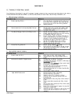
3.  Valve exhibits “excess” seat leakage.

NOTE:

 The Ranger QCT incorporates both a metal seal and a soft seal in many trim designs. For some options 

and trim designs the soft seal is omitted. Soft seals are never used in “reverse” flow direction.

Possible Cause

Remedy

A. 

Valve stroke limited mechanically.

A1. 

Loosen locking lever (59) and rotate 

             handwheel (58) CCW to its positive up-stop 
             position.  Retighten lock ing lever.
A2. 

Properly adjust actuator up-stop washer.

            NOTE:  DO NOT ADJUST THE ACTUATOR
            JAM   NUT (45) AND STOP SCREW (35).

B. 

Improper actuator bench setting.

B1. 

Calibrate  actuator  to  valve. 

B2. 

Ensure proper engagement of push rod 

             linkage from actuator to valve stem.

C. 

Excess trim wear.

C1. 

Erosive service, remove particulate from 

             services. 
C2. 

Use “ST6” trim designation numbers; flow to   

             be in “reverse” direction.
C3. 

Possible excess cavitation in liquid service.

             Change operation parameters. 
             Use anti-cavitation trim. 
C4. 

Incorporate trim using fluorocarbon elastomer 

             spac er. 
C5. 

Install abrasion sleeve.

 D.        Soft seal leakage

D1. 

Erosive service; remove particulate from 

             services. 
D2. 

If steam pressure exceeds 150  psig, switch to

             ST7 trim designation number.
D3. If 

T

1

 is greater than 400°F, switch to trim 


designation number S7. 

D4. 

Valve travel restricted; plug not “pulling into” 

             cage stops. 
D5. 

Wrong flow direction. Soft seal ONLY effective 

             in standard/forward flow direction. 
D6. Insufficient 

P. Soft seal is pressure energized.

E. 

Metal seal leakage

E1. 

Damaged seal due to debris in flow stream. 

 Replace 

seal.

E2. 

Over-temperature of soft seal; soft seal 

             deforms over edge of metal seal ring. 
             Remove soft seal or switch to trim designation 
             number ST7.
E3. 

Install fluorocarbon elastomer spacer if no soft

             seal is installed.
E4. 

Valve travel restricted; plug not “pulling into”

             cage stops. 
E5. 

Erosive wear. Replace seal. 

E6. 

High velocity. Check sizing for velocity & noise.

Summary of Contents for RANGER QCT

Page 1: ...T bodies sizes 4 6 and 8 mate with 150 and 300 lb RFFlanges Allsizesofflangelessconstructionmaybe installed between PN40 flanges Quick Change Trim QCT is furnished as a standard feature and allows use of several seal retainers and inserts to vary orifice size helpcontrolcavitationandreducenoise Alltrims use 90 plug rotation Disassembly inspection and reassembly of the trim can be accomplished easi...

Page 2: ...ng the completed piping system including the Ranger QCT valve to the max allowable CWP indicated on the valve s nameplate is acceptable If hydro test pressure is to exceed this limit the Ranger QCT must be removed before such testing Before pressurization the valve plug must be rotated out of the seat if of reverse ATO FC action WARNING The valve actuator unit should not be used as a step to suppo...

Page 3: ...Item Numbers that are with respect to IOM 48 or IOM148 will be in parenthesis and underscored i e 20 the same is true for the positioner parts All Item Numbers that are with respect to this IOM Ranger are not underscored i e 6 Body Size Reducer Size 150 Flgs 300 Flgs 600 Flgs L1 L2 L1 L2 L1 L2 1 DN25 None 8 38 213 Min 8 75 222 Min 8 94 227 Min 1 1 2 x1 Min 2 x1 Min 2 1 2 x1 7 38 187 1 1 2 DN40 Non...

Page 4: ...ges D Body Installation The Ranger QCT body can be installed between ANSI Class 150 300 or 600 lb RF or FF flanges ortheirISOequivalentofPN20 50or100 Socket weld weld neck or slip on companion flanges can be used Face to face dimensions are per ISA 75 08 02 1 Install valve so the flow direction matches the arrow on the valve body 2 For flangeless design alignment special bosses cast on the valve b...

Page 5: ...ngofnonreusable parts i e gaskets suitable solvents etc 3 Valves supplied from the factory do not use any aid to assist in gasket sealing such as oil sealant or pipe dope 4 Valves originally supplied per Opt 55 require special cleaning procedures Refer to Cashco Specification No S 1134 for details When in E Packing Check 1 Ensure that packing flange nuts 22 have not worked loose during shipment 2 ...

Page 6: ...onfirm greatest easiest movement of lower rod end 9 4 Remove the seal retainer screws 18 and washers 23 and 47 5 Remove the seal retainer 3 full orifice reduced anti cavitation lo noise sealretainer gasket 9 soft seal 10 if supplied and metal seal 11 6 Through backside of body 1 place a wooden hammer handle on the vane on the back side of the plug 6 or the LN2 LN4 lo noise insert 25 and tap lightl...

Page 7: ... 7 Ensure that the closing torque is nil i e actuator assembly AA linkage is loose or slack 6 Insertthecage plugsubassembly 2 4 5 6 into the body 1 On 1 1 2 and 2 sizes with lo noiseinsertsorabrasionsleeve makesure these pieces and the cage 2 slip together on the back of the cage 2 Make sure the tongue on the plug 6 stub shaft and the groove in the stem subassembly 7 mate together Check by looking...

Page 8: ...t be removed reinstalled and thenproperlycenteredtoprovideClassVIshutoff 10 On ATO FC and ATC FO Valves without handwheel 58 replace cover plate 20 and machine screws 36 Depressurize the actuator for ATC FO valves and disconnect temporary air supply 11 Return to Section III A through F for installation instructions NOTE All Sizes Reorient unit so that the back end of the body 1 is directed downwar...

Page 9: ...between yoke 12 and body 1 to assist in final orientation when re assembled 3 For live loaded construction a Loosenbothpackingflangenuts 22 until clearance exists between the bottom of the nut 22 and the retainer 28 b Spacer ring 29 should spin freely If stacked mechanism 27 28 29 is not loose due to corrosion debris packed dirt etc tap the spacer ring 29 lightly while attempting to pry up the spa...

Page 10: ...F sizes and 90 ft 122 N M for 8 HF size 4 Rotate stem 7 to ensure tongue and groove engagement with plug 6 m Usingasuitablesolventacceptabletotheowner thoroughly clean the valve stem 7 and the body s 1 stuffing box Inspect surface finish of stem subassembly 7 and internal wall finish of packing box bore at packing 13 area If deeply scratched corroded or pitted replace with new parts n It will be d...

Page 11: ... 1 through 3 previous Rotate stem 7 to plug s 6 closed position 2 Install trim in accordance with Subsection C Articles 1 through 10 previous 3 Install packing in accordance with Sub section G G Packing Replacement Remove stem as per Subsection D previous and proceed as follows 1 Secure body 1 in a vise with stem 7 vertical to the floor Reassemble stem 7 per appropriate Subsection E F or H 2 Never...

Page 12: ... packing nut 22 in alternating 1 2 revolution increments i Place each spring washer 27 stack over its packing stud 21 oriented as shown in Figure 9 j Place each spacer ring 29 over its packingstud 21 andspringwasherstack 27 oriented as shown in Figure 9 k Place each retainer 28 over its packing stud 21 oriented as shown in Figure 9 Ensure that each retainer 28 is properly positioned into each spac...

Page 13: ...e packing set 13 has been replaced checking each spacer ring 29 after each tightening When spacer ring 29 can no longer be rotated freely by fingers make an additional 1 2 revolution no furthertighteningshouldoccurtomaintain the live loaded intent of the design Overtighteningofthedesignasdescribed causes the mechanism to function as a jammed packing This will defeat the design intent of the mechan...

Page 14: ... of upset conditions and will be in automatic control SECTION V WARNING V STARTUP A General 1 Ensure that the Ranger QCT unit has been properly adjusted and calibrated including the positioner if installed per actuator maintenance manuals IOM 48 or 148 2 Recommend startup to be in manual mode This procedure assumes double block isolation and bypass valves for the control valve station See Figure 1...

Page 15: ...ator spring problems D1 Broken spring Replace all springs D2 Non symmetrical positioning of springs ensure that springs are symmetrical i e springs 180 across from each other 2 Valve exhibits excess vibration Possible Cause Remedy A Excess pressure drop A1 Bring pressure drop within design limits A2 Stage pressure drop using multiple valves in series B Excessive cavitation in liquid service B1 Cha...

Page 16: ...sible excess cavitation in liquid service Change operation parameters Use anti cavitation trim C4 Incorporate trim using fluorocarbon elastomer spacer C5 Install abrasion sleeve D Soft seal leakage D1 Erosive service remove particulate from services D2 If steam pressure exceeds 150 psig switch to ST7 trim designation number D3 If T1 is greater than 400 F switch to trim designation number S7 D4 Val...

Page 17: ...ors A Provide piping anchors and guides at control valve station Restrain bending movements B Incorrect line bolting B Use high strength line bolting heat treated alloy steel Opt 7A or corrosion resistant SST strainer hardened studs Opt 7C C Flange bolting unevenly loaded C1 Loosen and remove line bolting replace flange gasket and reinstall flange bolting See Table 3 Section III for line bolting t...

Page 18: ... typical format as follows last digit is alpha character that reflects revision level for the product PARTS KIT for FIELD REPAIR Contact your local Cashco Inc Sales RepresentativewiththeSerialNumberandProduct code Identify the parts and the quantity required to repair the unit from the BOM sheet that was provided when unit was originally shipped NOTE Those part numbers that have a quantity indicat...

Page 19: ...ize X Dimension 1 2 022 3 6 040 1 8 2 Item No Part Description 14 Packing Flange 15 Packing Follower Assy 15 1 Follower 15 2 Carbon Bushing Item No Part Description Item No Part Description 1 Body 15 Packing Follower 7 Stem Subassy 16 Follower Bushing Strip 8 Stem Retainer Subassy 17 Stem Retainer Screw 8 1 Retainer Sleeve 21 Packing Stud 8 2 Carbon Bushing 22 Packing Stud Nut 12 Yoke 27 Bellevill...

Page 20: ...Ring 31 Backup Ring 32 Tie Bolt 33 Nut used with Tie Bolt 43 Drive Screw Flanged Ranger 44 Flow Arrow Flanged Ranger 45 Security Seal 46 Caution Plate 47 Belleville Washer Recommended Spare Part Item No Part Description 1 Body 2 Cage 3 Seal Retainer 4 Bearing Long 5 Bearing Short 6 Plug 7 Stem Subassembly 8 Retainer Sleeve Subassembly 9 Seal Retainer Gasket 10 Seal Soft 11 Seal Metal 12 Yoke 13 Pa...

Page 21: ...tion Seal Retainer or LNA D Lo Noise Seal Retainer FIGURE 18 Abrasion Sleeve FIGURE 17 Reduced Trim Seal Retainer FIGURE 19 LN2 LN4 Lo Noise Insert Recess for washer 23 Centerline of valve stem 7 NOTE Seat retainer slot axis is always perpendicular to stem axis ...

Page 22: ...IOM Ranger 22 FIGURE 21 Slurry Trim FIGURE 20 Ranger Control Valve Line Bolting Used with 1 1 2 8 AT1 AT2 AT4 Trim FIGURE 22 Jammed Packing FIGURE 23 ATC FO Actuator Without Handwheel Assy ...

Page 23: ... cooling of the process gas depends on the process gas and the inlet and outlet pressures The system designer is responsible for determining whether the process gas temperature may raise under any operating conditions 2 Where the process medium is a liquid or semi solid material with a surface resistance in excess of 1GΩ special precautions shall be taken to ensure the process does not generate el...

Page 24: ... DA8 DA0 DA1 DAP SAP SLR 1 SLR 2 PTR 1 ALR 1 ULR 1 PGR 1 BQ BQ OPT 45 BQ CRYO 123 123 CRYO 123 OPT 45 123 OPT 46G 123 1 6 123 1 6 OPT 45 123 1 6 OPT 46G 123 1 6 S 123 1 6 S OPT 40 1000HP 1000HP OPT 37 1000HP OPT 45 1000HP OPT 45G 1000HP CRYO 1000HP 1 6 1000HP 1 8 1000LP 1000LP OPT 45 1000LP OPT 46G 6987 8310HP 8310HP 1 6 8310HP 1 8 8310LP 8311HP 8311LP 345 345 OPT 45 BA1 BL1 PA1 PL1 C BPV C PRV C ...

Reviews: