


IOM-3381/4381
5
equipped with Opt-4 Stabilizer will have the
u-cup stabilizer seal (30) removed when the
piston (16) is removed from body (1). Remove
stabilizer seal (30), if installed.
NOTE:
When piston (16) assemblies are
used with composition seats, Cashco, Inc.
does not recom mend attempting to remove
the composition seat. If composition seat is
damaged, replace entire piston assembly.
4. Clean flat mating surfaces of body (1) to body
cap (6) shoulder. Be careful not to scratch
either surface.
5. Clean debris from within the body (1) cavity.
Parts to be reused should be cleaned accord-
ing to owner's procedures.
NOTE: On valves
originally supplied as “oxygen clean”, Options
3381-5 & -55, 4381-36 & 55 maintenance
must include a level of cleanliness equal to
Cashco's cleaning stan dard #S-1134. For
regulators originally supplied as “cleaned for
Pharmaceutical and Food applications” Op-
tions 4381-37 and 4381-37S, maintenance
must include a level of cleanliness equal to
Cashco cleaning standard #S-1576.
Contact
factory for details.
6. If supplied with Opt-4 Stabilizer, install new
stabilizer seal (30) properly oriented onto
piston (16).
7. Slide the piston (16), including stabilizer seal
(30) if supplied, slowly into the body cavity.
Use thumbs to ease stabilizer seal(30) into
the body cavity.
8. Place piston spring (7) over spring hub of the
piston (16).
9. Apply pipe thread sealant to the body cap (6)
threads. Screw body cap (6) into body (1).
When body cap is fully down against body (1)
at the body cap (6) shoulder, impact the body
cap (6) into the body (1). This pressurized
joint is metal-to-metal joint with no gasket.
10. Bench test unit for suitable operation.
NOTE:
Regulators are not tight shutoff devices.
Even if pressure builds up beyond set point,
a regulator may or may not develop bubble
tight shutoff. In general, tighter shutoff can
be expected with composition seat.
11. Pressurize with air and spray liquid leak de-
tector to test around body cap (6) and body
(1) for leakage. Test pressure should be a
minimum of 100 psig (6.9 Barg) at the inlet.
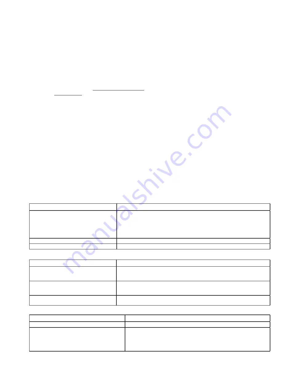
2. Regulator can't pass sufficient flow.
VII. TROUBLE SHOOTING GUIDE
1. Erratic operation; chattering.
SECTION VII
Possible Causes
Remedies
A.
Oversized regulator; inadequate rangeability. A1.
A2.
A3.
A4.
A5.
Check actual flow conditions, re-size regulator for minimum and maximum flow.
Increase flow rate.
Decrease regulator pressure drop; decrease inlet pressure by placing a throttling orifice
in inlet piping union.
Install next step higher range spring. Contact factory.
Before replacing regulator, contact factory.
B.
Worn piston; inadequate guiding.
B.
Replace trim ( possible body replacement).
C.
Weakened/broken piston spring.
C.
Replace piston spring. Determine if corrosion is causing the failure.
Possible Causes
Remedies
A.
Regulator undersized.
A1.
A2.
Confirm by opening bypass valve together with regulator.
Check actual flow conditions, re-size regulator; if regulator has inadequate capacity,
replace with larger unit.
B.
Incorrect range spring (screwing in CW of ad-
justing screw does not allow bringing pressure
level up to proper level).
B.
Replace range spring with proper higher range. Contact factory.
C.
Too much droop.
C1.
C2.
Review droop expected.
Contact factory.
3. Leakage through the spring chamber vent hole.
Possible Causes
Remedies
A.
Normal-life diaphragm failure.
A.
Replace diaphragm.
B.
Abnormal short-life diaphragm failure.
B1.
B2.
B3.
B4.
Can be caused by excessive chattering. See No. 1. to remedy chatter.
Can be caused by corrosive action. Consider alternate diaphragm material.
For composition diaphragms, ensure not subjecting to over-temperature conditions.
Downstream (outlet) pressure buildup occurring that overstresses diaphragms.
Relocate regulator or protect with safety relief valve.


