background image

6 - MAINTENANCE

Maintenance planning

Maintenance chart

Check

Drain fluid

Grease

Adjust

Replace

Cleaning

Change fluid

Maintenance action

Page no.

Break-in period

Engine oil and filter

x

6-17

Fuel filter

x

6-17

Hydraulic oil return filter

x

6-17

Pilot line filter

x

6-17

Travel reduction gears

x

6-18

Swing bearing

x

6-18

Grease points (Bucket)

x

6-18

Every 10 hours

Engine oil level

x

6-19

Engine coolant level

x

6-20

Hydraulic oil level

x

6-21

Fuel filter water separator

x

6-22

Fan and alternator drive belt

x

6-23

Every 50 hours

Grease points (Bucket)

x

6-24

Grease points (Boom and arm)

x

6-25

Grease points (Blade)

x

6-26

Track tension

x

6-27

Every 200 hours

Fuel filter water separator

x

6-29

Every 250 hours

Battery

x

6-31

Swing bearing

x

6-34

Tightening torques

x

6-35

Every 500 hours

Engine oil and filter

x

6-36

Fuel filter

x

6-38

Fuel filter water separator

x

6-39

Air cleaner

x

6-40

Radiator and coolers

x

6-43

Radiator fan

x

6-44

Travel reduction gears

x

6-44

Every 1000 hours

Hydraulic oil return filter

x

6-45

Pilot line filter

x

6-46

Travel reduction gears

x

6-47

Every 2000 hours

Engine coolant

x

6-48

Hydraulic oil suction filter

x

6-50

Hydraulic hoses

x

6-50

Every 5000 hours

Hydraulic oil

x

6-51

When necessary

Bulb replacement

x

6-53

Cab air filter

x

6-55

Fuel tank drain

x

6-56

6-15

Summary of Contents for CX37C

Page 1: ...ORIGINAL INSTRUCTIONS Mini Excavator OPERATOR S MANUAL CX37C Part number 48057994 1st edition English January 2017...

Page 2: ...2 12 Hand signals 2 13 California proposition 65 warning 2 17 Safety signs 2 18 3 CONTROLS AND INSTRUMENTS Access to operator s platform Door and steps 3 1 Operator s seat Operator s seat 3 4 Forward...

Page 3: ...rating the machine in hot or cold weather 4 6 Operating the machine 4 7 Lowering the attachment in the event of a failure 4 11 Bucket replacement 4 12 Hydraulic control lever operating pattern 4 13 Ca...

Page 4: ...ring battery charging or welding 6 14 Maintenance planning Maintenance chart 6 15 Break in period Engine oil and filter 6 17 Fuel filter 6 17 Hydraulic oil return filter 6 17 Pilot line filter 6 17 Tr...

Page 5: ...return filter 6 45 Pilot line filter 6 46 Travel reduction gears 6 47 Every 2000 hours Engine coolant 6 48 Hydraulic oil suction filter 6 50 Hydraulic hoses 6 50 Every 5000 hours Hydraulic oil 6 51 W...

Page 6: ...Troubleshooting 7 2 Other systems Troubleshooting 7 3 8 SPECIFICATIONS Machine specifications 8 1 Dimensions 8 4 Weights 8 7 9 ACCESSORIES Direct fit buckets 9 1 Auxiliary hydraulic circuits 9 2 Hydra...

Page 7: ...e used for work involving the use of special attachments accessories or equipment consult your CASE CON STRUCTION Dealer in order to make sure that any adaptations or modifications made are in keeping...

Page 8: ...owing transporting and lifting people is considered inappropriate and is prohibited Electro Magnetic Compatibility EMC Interference may arise as a result of add on equipment that may not necessarily m...

Page 9: ...o the control valves The control valves distribute the hydraulic fluid to the various cylinders and hydraulic motors employed A cooling system maintains the hydraulic fluid at normal operating tempera...

Page 10: ...or s cab SMIL16MEX1460AB 3 1 Designation Type Model Hydraulic Excavator___________________________ 2 Product Identification Number PIN ____________ SMIL16MEX1494AA 4 Engine The engine serial number A...

Page 11: ...etails regarding the engine only SMIL16MEX1291AA 7 Structure protection Roll Over Protective Structure ROPS Complies with ISO 12117 2 ISO 10262 LEVEL 1 1 Type of protective guard 2 Maximum machine mas...

Page 12: ...ation provided for that purpose below the operator s seat in the storage com partment Make sure it is always complete and in good condition If you wish to obtain extra copies or copies in languages ot...

Page 13: ...s manual to indicate the sides as they are seen from the operator s seat when the travel motors are positioned at the rear and the operator is facing the direc tion in which the machine advances forwa...

Page 14: ...omponents SMIL16MEX1477FB 1 1 Bucket 8 Oil cooler 2 Bucket tooth 9 Radiator 3 Boom swing cylinder 10 Engine 4 Tool box 11 Main pump 5 Swing motor 12 Hydraulic central joint 6 Fuel tank 13 Main control...

Page 15: ...5 Bucket control link 25 Muffler pipe 16 Side cutter 26 Counterweight 17 Bucket cylinder 27 Travel motor 18 Dipper 28 Sprocket 19 Dipper cylinder 29 Upper roller 20 Boom 30 Lower roller 21 Boom cylind...

Page 16: ...1 GENERAL INFORMATION 1 10...

Page 17: ...ot avoided could result in death or serious injury CAUTION indicates a hazardous situation that if not avoided could result in minor or moderate injury FAILURE TO FOLLOW DANGER WARNING AND CAUTION MES...

Page 18: ...num ber call the national number U S A and Canada only 1 888 258 0808 This number will direct you to the state or regional utility that assists with excavation activity NOTE Check with local authoriti...

Page 19: ...ved Always close access doors or panels before you operate the machine Dirty or slippery steps ladders walkways and platforms can cause falls Make sure these surfaces remain clean and clear of debris...

Page 20: ...ially around hot components such as the engine transmission ex haust battery etc More frequent cleaning of your ma chine may be necessary depending on the operating en vironment and conditions At leas...

Page 21: ...cting components are a certified system Any damage fire corrosion or modification will weaken the structure and reduce your protection If this occurs THE PROTECTIVE STRUC TURE MUST BE REPLACED so that...

Page 22: ...ed cables and other services Contact your local utilities or authorities as appropriate to determine the locations of services Make sure that the machine has sufficient clearance to pass in all direct...

Page 23: ...any other items which could get caught up in machinery Different types of job will require different types of pro tective equipment Items such as hard hats safety shoes heavy gloves reflector type jac...

Page 24: ...ON make sure the diameter of the pins and the width between the bucket lugs meet the dimensions needed to fit the quick coupler pins washers bushings etc Consult your CASE CONSTRUCTION Dealer Operatin...

Page 25: ...hat the machine the equipment and the tool are suitable for the work to be carried out 2 Make sure that the machine is in good condition and that servicing intervals are complied with 3 Check the trac...

Page 26: ...o avoid such risks Also before using these products read the manufacturer s instruc tions concerning their use If hydraulic fluid penetrates the skin call a doctor immediately Coolant solution is toxi...

Page 27: ...ided with the implement Implement operation and maintenance For the implement operation and maintenance refer to the operator s manual provided with the implement Safety area The safety area is the sp...

Page 28: ...e coolant mixtures engine oil hydraulic fluid brake fluid etc Do not mix drained brake fluids or fuels with lubricants Store all drained fluids safely until you can dispose of the fluids in a proper w...

Page 29: ...s with poor or impaired visibility Make sure that you and the signalman understand the signals to be used Start the engine PDE0002ATBP1 1 Shut down the engine PDE0002TBP1 2 Come to me Wave hands back...

Page 30: ...and forth PDE0005ATBP1 7 Emergency stop Wave hands back and forth PDE0005TBP1 8 Raise load or tool PDE0006ATBP1 9 Lower load or tool PDE0006TBP1 10 Slowly raise the load or tool PDE0007ATBP1 11 Slowl...

Page 31: ...ement stop moving hand and clench fist PDE0008ATBP1 13 Turn machine right swing load right To stop movement stop moving hand and clench fist PDE0008TBP1 14 Raise tool PDE0009ATBP1 15 Lower tool PDE000...

Page 32: ...2 SAFETY INFORMATION Retract dipper PDE0011ATBP1 19 Extend dipper PDE0011TBP1 20 Fill tool PDE0012ATBP1 21 Empty tool PDE0012TBP1 22 2 16...

Page 33: ...ITION 65 WARNING Diesel engine exhaust and some of its constituents are known to the State of California to cause cancer birth defects and other reproductive harm Battery post terminals and related ac...

Page 34: ...ble Clean safety signs with a soft cloth water and gentle detergent NOTICE do not use solvent gasoline or other harsh chemicals Solvents gasoline and other harsh chemicals may damage or remove safety...

Page 35: ...sign or other machine sign make sure you position it as shown below SMIL16MEX1512GB 1 Cab version A Cab door E Hydraulic tank and fuel tank B Cab window Right hand F Cowl support engine room C Consol...

Page 36: ...INFORMATION SMIL16MEX1513GB 2 Canopy version A Console box Left hand E Cowl support engine room B Counterweight F Accumulator of the solenoid valve C Console box Right hand D Hydraulic tank and fuel t...

Page 37: ...ous injury D0123A Location this signs is located on the counterweight Quantity 2 Part number 48018117 This sign cautions the operator that entry into the work range of the upper structure is forbidden...

Page 38: ...trate the skin and cause infection or other injury To prevent personal injury Relieve all pressure before discon necting fluid lines or performing work on the hydraulic system Before applying pressure...

Page 39: ...his sign warns to never touch the engine or the muffler when they are still hot SMIL16MEX0361AA 7 4 Lifting location Location these signs are located on the boom Quantity 2 Part number 48019079 This s...

Page 40: ...nning Turn off the en gine and relieve all pressure from pressurized systems before servicing the machine Failure to comply could result in death or se rious injury W0905A Location this sign is locate...

Page 41: ...ea Keep the battery away from sparks open flames and other ignition sources Never charge a frozen battery Failure to comply could result in death or se rious injury W0005A WARNING Improper operation o...

Page 42: ...2 Part number 48028291 This sign warns the operator that entry into the work range of the attachment is forbidden while the engine is running SMIL16MEX0003AA 12 9 Combined hydraulic attachment sign L...

Page 43: ...k lever in the raised position 3 Stop the engine 4 Remove the key SMIL16MEX0015AA 15 12 Safety front window Location these signs are located on the both side window of the cab Quantity 2 Part number 4...

Page 44: ...how to use the emer gency exit right hand side window In case of emergency use the hammer to break the right hand side window of the cab SMIL16MEX0012AA 18 15 Emergency stop of the engine Location th...

Page 45: ...Keep fuel away from flames or sparks Shut off engine and remove key before servicing Always work in a well ventilated area Clean up spilled fuel immediately Failure to comply could result in minor or...

Page 46: ...by changing the position of the lever pattern How to use 1 Loosen the bolt 1 or 2 2 Move the lever to the ISO or SAE position 3 After setting the pattern tighten the bolt to secure the lever NOTE tig...

Page 47: ...is located on the right hand side window of the cab Canopy location this sign is located on the right hand side of the canopy Quantity 1 Part number 48018423 This sign shows that work near overhead h...

Page 48: ...bar 450 psi High heat will cause the safety plug to blow out of the accumulator and the escap ing nitrogen will propel the accumulator at a dangerous rate of speed Failure to comply could result in d...

Page 49: ...the hydraulic tank Quantity 1 Part number 48019086 This sign warns you to fill only hydraulic oil and not to not fill the diesel fuel SMIL16MEX0014AA 29 26 Water separator Cab location this sign is l...

Page 50: ...efore you transport the machine SMIL16MEX0011BA 31 28 Engine control ideogram Location this sign is located on the left hand console box Quantity 1 Part number 48019102 This signs describes the engine...

Page 51: ...located on the dozer blade Quantity 2 Part number 48019104 This sign shows the location where a sling is attached to handle the excavator and the coupling location when the machine has to be transpor...

Page 52: ...ging the gas Quantity 1 This sign indicates that the vehicle uses a fluorinated greenhouse gas and shows 1 The designation for such gas 2 The quantity of the gas included on the air conditioning syste...

Page 53: ...Cab door CAUTION Pinch hazard Be careful not to get your hand clothes etc caught in the door when closing it Failure to comply could result in minor or moderate injury C0046A To open the door use the...

Page 54: ...can be latched in completely open position To latch or unlatch the door operate the lever 3 NOTICE do not leave the door ajar Fix it in a latched position Before performing work with the door open loc...

Page 55: ...s injury W0141A WARNING Fall hazard When entering or exiting the cab never use the control levers as handholds Always mount and dismount the machine in a safe way Maintain a three point contact with s...

Page 56: ...seat can be positioned over a range of 52 mm 2 in SMIL16MEX0033AA 1 Seat back angle adjustment Hold the lever B in the raised position Move with the seat back to the desired position Release the lever...

Page 57: ...o comply could result in death or se rious injury W0046C Sit comfortably on the operator s seat Pull out a long section of belt D Engage the belt in the fastening system E NOTE if the section of belt...

Page 58: ...ontrols pattern and change the position of the valve accord ingly Refer to page 4 13 Control levers Pattern ISO type Left hand control lever 1 The dipper arm extends 2 The dipper arm retracts 3 The up...

Page 59: ...s 7 The bucket retracts filling 8 The bucket extends dumping NOTE the movement speed of the boom or of the bucket depends on the control lever tilt angle In the intermediate position two movements can...

Page 60: ...peed of the arm or of the swing depends on the control lever tilt angle In the intermediate position two movements can be obtained simultaneously NOTE when the upper structure swing control is re leas...

Page 61: ...etracts 7 The bucket retracts filling 8 The bucket extends dumping NOTE the movement speed of the boom or of the bucket depends on the control lever tilt angle In the intermediate position two movemen...

Page 62: ...achine around its center axis a d opposite simultaneous rotation of the tracks with consequent clockwise rotation of the machine around its center axis a b c d positions to move one track only Con seq...

Page 63: ...ion Press the pedal to left hand side 2 to swing the boom to the left hand direction NOTICE make particular attention when swing the boom to the left hand side the attachment may collide with the cab...

Page 64: ...3 CONTROLS AND INSTRUMENTS Footrest SMIL16MEX1264BA 17 3 12...

Page 65: ...me Move the grips 1 to the inside to release the lock latches Hold both grips 1 and push the windshield upward Hold both grips 1 and back into the storage position Release both grips carefully until t...

Page 66: ...3 6 3 Armrest 4 Engine speed control switch refer to page 3 16 5 Main light switch This switch activates the head light and the work light in two steps The first step activates the head light and the...

Page 67: ...g sys tem activation switch is pressed to disengage the moving hook The buzzer stops when the switch is released to engage the moving hook To connect or disconnect an attachment proceed as follows 1 P...

Page 68: ...osition A all the functions are disabled NOTICE never use the safety lock lever as a hand hold when get in or out the machine B Unlocked position when the safety lever 1 is in un locked position B the...

Page 69: ...tion NOTICE do not break the windshield of the cab except when it is absolutely necessary such as to escape in an emergency WARNING Avoid injury A safety sign indicates which window to use as an emerg...

Page 70: ...electric pump which is operated from the wiper and washer switch NOTICE never operate the windshield washer control when the reservoir is empty This could cause damage to the electric pump Remove the...

Page 71: ...to page 9 12 9 Auto idle 10 Cigarette lighter and 12 V power supply socket the device is active with the starter key in ON position or while the engine is running To operate the cigarette lighter pus...

Page 72: ...the red warning light in the instrument cluster is OFF SMIL16MEX0390AA 2 Travel alarm switch optional The travel alarm switch 7 when pressed activates a buzzer to alarm surrounding the machine when th...

Page 73: ...the weather temperature is below 10 C 50 F until the pre heat light on the instrument cluster turns OFF NOTE the starter key is also used to lock the cab door the side hoods and the storage compartmen...

Page 74: ...of soft soil or mud Do not forcibly push down or dig deeply with the blade When operating in an area with many rocks and stones pay attention not to damage the blade NOTICE during blade operations avo...

Page 75: ...on this machine does not en tirely guarantee the condition of the machine Daily in spection should be performed When the cluster provides a warning immediately check the problem and perform the requi...

Page 76: ...SMIL16MEX0379AA 2 2 Fuel gauge The fuel gauge indicates the amount of fuel in the fuel tank The red range A and the warning light B turn ON and a buzzer sounds when the level of fuel is below 5 5 L 1...

Page 77: ...rned OFF the red light 5 turns OFF and the buzzer stops SMIL16MEX1501AA 6 6 Engine oil pressure warning light The engine oil pressure warning red light 6 is ON and the buzzer sounds when the oil press...

Page 78: ...ight 9 is ON when the ma chine is overloaded The overload warning alarm is in tended to avoid lifting of excessive loads SMIL16MEX1501AA 10 10 Up left hand button Press the button 10 to navigate up or...

Page 79: ...er stop button Press the button 13 to select the menu Press the button 13 to stop the buzzer when the buzzer sounds SMIL16MEX1501AA 14 14 High speed travel light The high speed travel light 14 is ON w...

Page 80: ...3 CONTROLS AND INSTRUMENTS Air conditioning control SMIL16MEX2336FB 1 1 Fan switch 2 Temperature control switch 3 Outlet control louver air conditioner only 3 28...

Page 81: ...ir temperature turn clockwise the tem perature control switch To increase the air temperature turn counterclockwise the temperature control switch SMIL16MEX2338AA 3 Outlet control louver The outlet co...

Page 82: ...eeds of ventilation The first step activates the low fan speed of ventilation The second step activates the high fan speed of ventila tion The outlet control louvers 2 if open allows you to control th...

Page 83: ...NSTRUMENTS Rearward controls Storage compartment Located below the operator s seat this compartment is used to store various objects Lock and unlock the storage compartment with the starter key SMIL16...

Page 84: ...close the door The room light selection switch is equipped to select either one of the following status OFF the light is turned off always ON the light is turned on always NOTICE make sure that the c...

Page 85: ...L button 3 MODE button 4 Audio MUTE button 5 AM FM selection button 6 UP DOWN tuning button 7 Pre set memory buttons 8 Pre set scan PS Best Station Memory BSM button 9 USB function 10 Auxiliary AUX fu...

Page 86: ...eturn to normal indication in 5 s after the last adjust ment is made or when another function is activated SMIL16MEX3084AA 3 BASS control To adjust the bass level first select the bass mode by pressin...

Page 87: ...in 5 s after the last adjustment or when another function is activated 3 Mode button Press the mode button A to select RADIO USB AUX audio SMIL16MEX3084AA 4 4 Audio mute button Press the audio mute b...

Page 88: ...r curve as desired SMIL16MEX3084AA 7 13 Loud button When listening to music at low volume levels this feature will boost the bass and treble response This action will compensate for the reduction in b...

Page 89: ...P ID3 v2 display 2 Pre set memory button 2 SCN File scan 3 Pre set memory button 3 RPT Repeat play selector 4 Pre set memory button 4 RDM Random play selector 5 Pre set memory button 5 D Directory dow...

Page 90: ...cy Press the BSM button A momentarily again to remain on the station currently being heard Best station memory BSM Press the BSM button A for longer than 2 s to activate the BSM tuning feature which w...

Page 91: ...hold the cue button A to advance rapidly in the forward direction or the review button B to ad vance rapidly in the backward direction SMIL16MEX3084AA 14 MP3 directory file searching The D button A an...

Page 92: ...in to cancel the function The unit will then play the selected file NOTE in case of playing MP3 file when the SCN scan button is pressed and held for longer than 2 s the SCN mark will blink on the LCD...

Page 93: ...play all files in directory randomly until the directory random mode is cancelled by press ing the random button again or by activating the scan or repeat functions RDM mark will disappear from LCD sc...

Page 94: ...death or serious injury W0238A Side hood The side hood A allows to access to the compartment including the hydraulic oil tank the fuel tank the filling plug of the radiator coolant and the battery dis...

Page 95: ...rtment SMIL16MEX1438AA 3 Closing 1 Lightly lift up the side hood lower the lifting stem and use the handle to lower the side hood gently NOTICE when you lower the hood make sure that the hood does not...

Page 96: ...Position the mirror A on the bracket B as shown in the figure aside Horizontally adjust the mirror location in order to maximize visibility The mirror inclination depends on the height both of the sea...

Page 97: ...tally adjust the mirror location in order to maximize visibility The mirror inclination depends on the height both of the seat and the operator SMIL16MEX1511BB 3 Vertically adjust the mirror location...

Page 98: ...eared SMIL16MEX1439AA 1 Place the battery disconnect switch in the I position dur ing normal operation Place the battery disconnect switch in the O position only during the following operations 1 Batt...

Page 99: ...Never fill the tank when the engine is running 3 Wipe up spilled fuel immediately Failure to comply could result in death or serious injury W0099A Use the starter key to unlock the door 1 located in t...

Page 100: ...oisture elimination product water draining agent in the fuel tank because It may damage the engine NOTE in cold weather use fuel corresponding to the am bient temperature NOTICE in cold weather fill t...

Page 101: ...lways mode the password is required whenever the operator start the engine Interval mode the password is required when the op erator starts the engine first The operator can restart the engine within...

Page 102: ...4 OPERATING INSTRUCTIONS Password change To change the password input 5 to 10 digits and press Enter 1 Delete 2 Enter NOTE the default password is 00000 SMIL16MEX0384AA 2 4 2...

Page 103: ...WARNING Toxic gas and asphyxiation hazard Diesel exhaust contains dangerous compounds Never operate the engine in a closed building or area Proper ventilation is required under all circumstances Fail...

Page 104: ...it has been cranked up Release the starter key as soon as the engine is run ning regularly SMIL16MEX1501AA 5 NOTICE the cranking up of the engine may be difficult in severe winter climates If the engi...

Page 105: ...er to mid range speed 3 Set the safety lock lever to UNLOCK position frontward position 4 Operate the bucket control lever for 5 min NOTICE do not operate any control lever except the bucket control l...

Page 106: ...rdless of service due Tightly close the breather cap of the hydraulic tank to prevent invasion of sand and dust to the hydraulic circuits Make sure to thoroughly clean the grease fittings before greas...

Page 107: ...as pipes water pipes and underground installations may cause serious injury If the work takes place adjacent to high voltage power lines make sure to check the following work range Less than 57000 V 4...

Page 108: ...hydraulic systems NOTICE do not exceed the machine performance It may result in accident or failure NOTICE perform lifting operations within the specified load limit The turret swings when the left c...

Page 109: ...ing on slopes in order to understand proper operating practices and precautions for traveling along slopes NOTICE The machine grade ability is 30 58 Never operate the engine when the incline of the ma...

Page 110: ...ing force of the bucket if necessary SMIL16MEX1540AB 3 2 The digging resistance and wearing of tooth can be reduced by putting the end of bucket tooth to the digging direction SMIL16MEX1541AB 4 3 Do n...

Page 111: ...et or attachment when lowering the bucket or attachment In cases where the machine fails and the engine stops lower the attachment using the procedure described in this manual Failure to comply could...

Page 112: ...1 3 Remove the stopper bolts 1 and the nuts 2 then remove the pins 3 from the arm B and the pin 4 from the link C 4 Remove the bucket A NOTE after the removal of the pins make sure that they are not c...

Page 113: ...e machine check which control function is active Failure to comply could result in death or serious injury W0185A NOTICE whenever a change is made to the machine control pattern also replace the patte...

Page 114: ...can easily be changed to the ISO type I or the SAE type A by changing the position of the lever pattern 1 located on the pattern change valve V To change the pattern perform the following operations...

Page 115: ...pe Left hand control lever control function 1 Boom lowering 2 Boom raising 3 Swing left hand 4 Swing right hand SMIL16MEX3077AB 7 Right hand control lever control function 5 Arm out 6 Arm in 7 Bucket...

Page 116: ...on Smooth operation Low noise Harmless for paved road Easy handling Resistant Large traction force Excellent Good Normal Rubber track warranty The warranty does not cover such damages to the rubber tr...

Page 117: ...it in a closed room where it will not be exposed to direct sunshine or rain LELI11E0262AA 4 When the machine travels only on one side of the track and keeps the other side floating the track may come...

Page 118: ...e substances wash them with water The rubber tracks have to be used with a temperature range between 25 C 13 F and 55 C 131 F NOTE Use the rubber tracks under proper tension to prevent them from comin...

Page 119: ...his will risks to damage the rubber track Both ma chine sides must travel at the same level LELI11E0269AB 11 Do not change the direction of the machine with the rubber tracks positioned on earth heaps...

Page 120: ...ine seizing Stop the engine after the engine temperature has dropped NOTICE make sure to run the engine in idling status before completely stopping it except for emergency 4 Turn the starter key to th...

Page 121: ...e speed before you start trav eling In order to maximize visibility fully retract the arm and completely close the bucket NOTICE before start traveling make sure to fully raise the blade in order not...

Page 122: ...line travel reverse travel Press the two pedals or pull the two levers rearwards at the same time SMIL13CEX2680AB 4 Turning to the left forward travel Press the right hand pedal or push the right hand...

Page 123: ...ear wards SMIL13CEX2684AB 8 Turning on the spot to the right Press the left hand pedal or push the left hand lever for wards and at the same time press the right hand pedal or pull the right hand leve...

Page 124: ...the location of the travel unit before you start traveling 2 Select ground as flat and solid as possible for travel ing 3 Bypass obstructions during travel 4 Travel with decreased traveling speed on...

Page 125: ...in sys tems LELI11E0219AB 12 LELI11E0218AB 13 For uphill and downhill travel approach the slope as out lined in the pictures The undercarriage shall be oriented along the slope with the blade facing t...

Page 126: ...to the low idle position and then start the engine again If the engine does not start remove the starter key and place the Do not operate tag on the machine controls Get off the operator s compartment...

Page 127: ...on the steps Failure to comply could result in death or serious injury W0141A Always park the machine on a level and firm ground Orient the upper structure frame parallel to the under carriage The fro...

Page 128: ...eres public road LELI11E0241AB 3 If parking on a slope is unavoidable orient the undercar riage along the slope and lower and indent the bucket 1 and the dozer blade 2 into the ground Follow the park...

Page 129: ...ear loading type trailer is used for road transport make sure that ramps are available to climb onto the trailer bed Use ramps which have sufficient width length thickness and strength The ramp slope...

Page 130: ...to reach the resting position giving particular attention to the attachment so as not to touch the trailer bed SMIL16MEX0403AA 2 3 Stop loading when the machine is located horizontally in the trailer...

Page 131: ...Set the safety lever to rearward position LOCK po sition 5 Turn off the engine and remove the starter key 6 Get off the machine 7 Use the starter key to close and secure the cab door the engine access...

Page 132: ...rt the engine 5 Select the low travel mode 6 Raise the dozer blade and operate the arm and bucket controls so the bottom of the bucket is about 20 cm 7 9 in above the trailer bed NOTICE in this positi...

Page 133: ...ting equipment is in good condition and all hooks are equipped with safety latches Failure to comply could result in death or serious injury W0256A WARNING Crushing hazard This operation may be danger...

Page 134: ...wire rope and stay to keep safety distance from the machine avoiding the touch with the machine 4 Put a rubber plate where the wire ropes touch the ma chine to prevent damage NOTICE it is imperative t...

Page 135: ...comply could result in death or serious injury W0259A As far as possible try to carry out repairs on spot or consult your CASE CONSTRUCTION Dealer NOTICE the machine must be towed very slowly over a s...

Page 136: ...5 TRANSPORT OPERATIONS 5 8...

Page 137: ...specifications Improperly or incorrectly performed maintenance and repair voids the equipment warranty and may affect service intervals Respect the maintenance intervals by checking the hour meter eve...

Page 138: ...and nuts are correctly tightened Wipe off any dust engine operator s compartment etc Check for any signs of damage Engine Check the oil level and change the oil if necessary Check the coolant level Ch...

Page 139: ...fumes normal Any strange noises Check for abnormal noise on the hydraulic components Check the components for signs of leaking oil or water Check the audible alarm devices working lights and windshie...

Page 140: ...67 provides specifications for biodiesel blends from B6 to B20 Pure biodiesel B100 specification is covered by the following requirements ASTM D6751 Standard specification for biodiesel fuel blend sto...

Page 141: ...diesel Board for producers and marketers of biodiesel fuel See the National Biodiesel Board website at www biodiesel org for more information Storage The machine should not be stored for long periods...

Page 142: ...gal CASE AKCELA NO 1 ENGINE OIL SAE 15W 40 MS 1121 SAE 15W 40 ACEA E7 E5 API CI 4 Travel reduction unit 0 5 L 0 13 US gal x2 CASE AKCELA GEAR 135 H EP 80W 90 MAT3511 SAE 80W90 API GL 5 CASE AKCELA ACT...

Page 143: ...engine cooling system in the above mentioned operating temper ature range of the machine CASE AKCELA ACTIFULL OT EXTENDED LIFE COOLANT is available as 50 50 PREMIXED coolant solution ready for usage C...

Page 144: ...perating in severe winter climate consult the fuel supplier or the CASE CONSTRUCTION dealer for specific diesel fuel to be used The diesel fuel to be used on the machine shall be free from dust partic...

Page 145: ...collecting oil to be replaced is not leaking Never spread fluids or lubricants on the ground or into water Consult the CASE CONSTRUCTION dealer or the Local Environmental Agency in order to obtain inf...

Page 146: ...commended operating temperature range H 15W 40 API CI 4 40 C 40 F 30 C 22 F 20 C 4 F 10 C 14 F 0 C 32 F 10 C 50 F 20 C 68 F 30 C 86 F 40 C 104 F 50 C 122 F H Engine oil pan or coolant block heater rec...

Page 147: ...Failure to comply could result in death or serious injury W1044A 1 Place the machine on a flat and level ground Lower the attachment to the ground and stop the engine 2 Put the safety lever in UNLOCK...

Page 148: ...t to rear a dozen times approximately NOTE this procedure does not completely release the pressure so when working on the hydraulic system loosen the connections slowly and do not stand in the directi...

Page 149: ...water sep arator 1 SMIL16MEX3172AB 2 5 Loosen the air vent plug 5 located on the fuel filter 2 6 Tighten the air vent plugs 4 and 5 when bubbles do not come up any more 7 Open the air vent cock locate...

Page 150: ...g apparatus ground cable to the com ponent on which the welding operation is to be performed Never connect the welding apparatus to the undercarriage when welding on the upper structure or vice versa...

Page 151: ...x 6 24 Grease points Boom and arm x 6 25 Grease points Blade x 6 26 Track tension x 6 27 Every 200 hours Fuel filter water separator x 6 29 Every 250 hours Battery x 6 31 Swing bearing x 6 34 Tighten...

Page 152: ...6 MAINTENANCE Check Drain fluid Grease Adjust Replace Cleaning Change fluid Maintenance action Page no Fuel tank strainer x 6 57 Control levers x 6 58 Plastic and resin parts x 6 58 6 16...

Page 153: ...38 Hydraulic oil return filter Replace the hydraulic oil return filter after the first 250 h of service then replace the hydraulic oil return filter ev ery 1000 h To replace the hydraulic oil return f...

Page 154: ...ace the travel reduction gears oil perform the operations described on page 6 47 Swing bearing Grease the swing bearing after the first 50 h then every 250 h To lubricate the swing bearing refer to pa...

Page 155: ...einsert the dipstick 1 into the guide tube as far as it will go and then take it out 3 The engine oil level is optimal when the level is between the lower minimum and the upper maximum marks A 4 If th...

Page 156: ...ing the filler cap while the system is hot Before removing the cap completely cover the cap using a thick cloth and slowly open the filler cap to allow the pressure to escape Do not add cold water to...

Page 157: ...ter key SMIL16MEX0376AA 1 2 Open the side hood to access the hydraulic oil tank 3 The oil level is normal if between the red lines of the level gauge 1 3 If the hydraulic oil level is not in the corre...

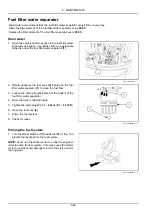
Page 158: ...wise the fuel cock 2 located on the fuel filter water separator 1 to close the fuel flow 3 Loosen the drain plug 3 located at the bottom of the fuel filter water separator 4 Drain the water collected...

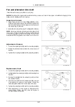
Page 159: ...be replaced if it is elongated it has cracks or it is worn out SMIL16MEX0418AA 1 Adjustment of tension 1 Loosen the adjusting bolt 1 and the mounting bolt 2 2 Rotate the alternator 3 to obtain the co...

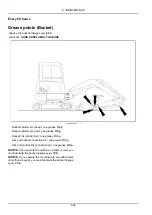
Page 160: ...in rod one grease fitting Bucket link control rod one grease fitting Arm and bucket connection pin one grease fitting Arm and control link connection pin one grease fitting NOTICE if you operate the m...

Page 161: ...om cylinder head and rod side two grease fittings Arm cylinder pin head and rod side two grease fittings Boom and arm connection pin one grease fitting Boom swing cylinder head and rod side two grease...

Page 162: ...AKCELA MOLY GREASE SMIL16MEX0420FA 1 Dozer blade connection pin two grease fittings Dozer blade cylinder pin two grease fittings NOTICE if you operate the machine in water or mud you must lubricate th...

Page 163: ...the engine speed lever to the maximum speed position 3 Operate the travel control lever to move the raised track forward and backward and shake off the mud 4 Repeat the same operations for the other t...

Page 164: ...or seri ous injury W0261A To reduce the tension 1 Loosen the grease fitting adapter and drain grease from the cylinder 2 When the track tension is correct tighten the grease fitting adapter 3 Clean t...

Page 165: ...a container with an ap propriate capacity under the fuel filter water separator 1 SMIL16MEX1445AA 1 2 Close the fuel cock 1 of the fuel filter water separator 3 Loosen the drain cock 2 at bottom of th...

Page 166: ...lling Clean spilled fuel 4 Remove the floating ring 5 from the cup 5 Remove the filter element 6 clean and replace if nec essary 6 Empty the cup 4 and rinse the inside with kerosene 7 Install a new fl...

Page 167: ...tention immediately Failure to comply could result in death or serious injury W0111A WARNING Battery gas can explode To prevent an explosion 1 Always disconnect the negative battery cable first 2 Alwa...

Page 168: ...If the battery voltage is less than the factory spec ification check the battery specific gravity and recharge the battery Battery voltage more than 12 V 1 Positive terminal 2 Negative terminal SMIL1...

Page 169: ...re that the starter key of the machine with the charged battery is in OFF position 1 Connect the red terminals R of booster cable to the battery terminals between exhausted bat tery positive terminal...

Page 170: ...cant CASE AKCELA 251H EP MULTI PURPOSE GREASE Swing bearing two grease fittings Using a grease gun inject grease of the specified type in the grease points shown in figure SMIL16MEX0940AA 1 1 Boom swi...

Page 171: ...1 75 96 3 155 9 N m 71 115 lb ft Turning joint mounting bolt and nut M10 x 1 5 54 2 81 3 N m 40 60 lb ft Hydraulic system Swing motor mounting bolt M14 x 2 0 164 1 221 N m 121 163 lb ft Swing bearing...

Page 172: ...ne on a flat and level place Stop the engine remove the starter key 2 Remove the cover of drain plug 3 Place a container with a capacity of 10 L 2 6 US gal under the drain plug 4 Remove the drain plug...

Page 173: ...al A Open B Close 9 Install the drain plug SMIL16MEX1443AB 4 10 Add new engine oil to the engine Install the fill cap 11 Run the engine for several minutes to check that there are no leaks at the filt...

Page 174: ...ions Do not use gloves Do not open the packaging for the filter kit until you start the installation work Do not reuse any fuel remaining within the cover For persistent dirt within the cover wipe it...

Page 175: ...filter gasket before tighten it 7 Connect the fuel hoses 3 and install the clamps 2 to the fuel filter 1 8 Loosen the air vent plug 4 to let the air out Start engine and check for fuel leakage 9 Bleed...

Page 176: ...ury C0049A Clean the air filter every 500 h or when the air cleaner warning light appears on the instrument cluster Replace the primary air filter element after four times cleaning Replace the seconda...

Page 177: ...mes out of the primary element cleaning is complete NOTE be sure to keep the compressed air pressure below 3 bar 44 psi SMIL14CEX2795AA 5 NOTE do not use compressed air if there is oil or soot in the...

Page 178: ...d and must be changed SMIL16MEX1532AA 8 7 Install the secondary element and the primary element into the air cleaner 8 Install the cover 1 SMIL16MEX1530AA 9 9 Lock the two fastener 2 NOTICE the air fl...

Page 179: ...occur if the radiator fin or the oil cooler fin is clogged NOTE after working in a dusty place clean radiator more frequently 4 Use compressed air to blow away mud or dirt that have clogged the radiat...

Page 180: ...bricant CASE AKCELA GEAR 135 H EP 80W 90 1 Park the machine on flat horizontal ground 2 Move the machine so that the drain plug 1 comes down to the lowest position 3 Stop the engine and remove the sta...

Page 181: ...ly could result in death or serious injury W0905A Replace the hydraulic oil return filter every 1000 h 1 Release all the pressure in the hydraulic tank Refer to page 6 11 2 Clean the top of the hydrau...

Page 182: ...ly could result in death or serious injury W0905A Replace the pilot line filter every 1000 h After 250 h of operation in run in period NOTICE when the machine is a new vehicle or when the main compone...

Page 183: ...vel plug 2 6 Remove the drain plug 1 NOTE check the condition of the drained oil If there are pieces of metal or foreign objects in the oil consult the CASE CONSTRUCTION dealer 7 Replace the O ring se...

Page 184: ...proceeding Failure to comply could result in death or serious injury W1469A Replace the engine coolant every 2000 h Fluid CASE AKCELA ACTIFULL OT EXTENDED LIFE COOLANT Quantity antifreeze water mixtur...

Page 185: ...t filter SMIL16MEX1458AA 3 11 Operate the engine for 5 min and let the coolant tem perature arrives above 80 C 176 F 12 Stop the engine and drain the cooling system NOTE if the water being drained is...

Page 186: ...stall a new O ring 4 and install the oil suction filter on the suction cover 2 Lock the suction cover 2 with the four bolts 1 Tighten the bolts 1 to 55 83 N m 40 6 61 2 lb ft 6 Check the hydraulic flu...

Page 187: ...To prevent personal injury Relieve all pressure before disconnecting fluid lines or per forming work on the hydraulic system Before applying pressure make sure all connections are tight and all compo...

Page 188: ...the air bleed plug at top of the hydraulic pump Loosen the air bleed plug If no fluid comes out remove the plug and fill the pump with new clean hydraulic fluid 10 Tighten the air bleed plug on the hy...

Page 189: ...flat screwdriver to remove the protective glass of the ceiling light in order to access the bulb 1 SMIL16MEX1117AA 1 2 Remove the bulb and install a new one of the same wattage in the ceiling light 3...

Page 190: ...ll the clip outwards 1 and remove the bulb 2 SMIL16MEX0937AA 5 4 Install a new bulb of the same wattage in the working light NOTE make sure of the correct position of the bulb 5 Push the clip inwards...

Page 191: ...ter when necessary 1 Stop the engine before remove the cab heater filter 2 Remove the screws 1 and the heater cover 2 on the right hand side of cabin 3 Remove the cab heater filter 3 4 Clean the cab h...

Page 192: ...ult in death or serious injury W0099A Drain water and sediment from the fuel tank when necessary NOTE take all necessary precautions during the following operations no foreign matter must enter the fu...

Page 193: ...d inside the fuel filler neck 3 Inspect the fuel tank strainer for damage If damaged discard and replace If in good condition clean it in an environmentally safe manner NOTE diesel fuel is a preferred...

Page 194: ...parts Y 3 Repeat the same operation for the other hydraulic con trol lever SMIL16MEX0443BA 1 Plastic and resin parts Use a soft slightly humid cloth to clean the panels the consoles and the switches...

Page 195: ...r s seat The fuse box cover indicates the function and amper age of each fuse NOTICE before changing fuses or relays turn the starter key to the OFF position NOTICE never replace a fuse with a fuse of...

Page 196: ...20 A 9 Radio monitor B 20 A 2 Horn cigar preheat 20 A 10 Radio monitor 10 A 3 Safety EPPR 20 A 11 ECU 30 A 4 Starter Alternator 20 A 12 Aircon heater 30 A 5 Opt travel 20 A 13 Work light 20 A 6 Spare...

Page 197: ...the machine resumes service the film will disappear automatically 5 While the engine is still warm drain the oil sump re place the oil filter and fill with specified oil Check the oil level and add mo...

Page 198: ...recharge the batteries if re quired 2 The levels and top up if necessary 3 The condition of all lines connectors and clamps rust Grease if necessary 4 The condition of the paintwork Apply a coat of a...

Page 199: ...tion of the air conditioning drive belt and replace it if necessary if equipped 7 Check the cooling system level and add more coolant if necessary 8 Check the hydraulic fluid level and supply it as ne...

Page 200: ...6 MAINTENANCE 6 64...

Page 201: ...your authorized dealer Incorrect tightening torque of radiator cap Tighten the radiator cap firmly or replace the packing of it Defect in cluster See your authorized dealer The engine does not start w...

Page 202: ...d to START Damaged wiring See your authorized dealer Battery not charged Charge the battery Damaged starter motor See your authorized dealer Damaged safety relay See your authorized dealer The pinion...

Page 203: ...the sprocket Incorrect tension of track Adjust tension of track Bucket either rises slowly or not at all Low oil level Add oil to specified level Slow speed of travel swing boom arm and bucket Low oi...

Page 204: ...7 TROUBLESHOOTING 7 4...

Page 205: ...High idling speed 2280 2380 RPM Low idling speed 1150 1250 RPM Rated fuel consumption 177 g Hp hr at 2200 RPM Starting motor 12 V 2 3 kW Alternator 12 V 55 A Battery 1 x 12 V x 70 A h 20 h rating Main...

Page 206: ...meter x Stroke 85 mm 3 3 in x 45 mm 1 8 in x 540 mm 21 3 in Boom cylinder Cushion Extend only Bore diameter x Rod diameter x Stroke 80 mm 3 1 in x 45 mm 1 8 in x 585 mm 23 0 in Arm cylinder Cushion Ex...

Page 207: ...8 SPECIFICATIONS Number of rollers and shoes on each side Upper roller 1 Lower roller 4 Track shoes 44 8 3...

Page 208: ...clearance 290 mm 11 4 in I Rear end distance 870 mm 34 3 in I Rear end swing radius 870 mm 34 3 in J Distance between tumblers 1700 mm 66 9 in K Undercarriage length 2130 mm 83 9 in L Undercarriage w...

Page 209: ...arance 290 mm 11 4 in I Rear end distance 870 mm 34 3 in I Rear end swing radius 870 mm 34 3 in J Distance between tumblers 1700 mm 66 9 in K Undercarriage length 2130 mm 83 9 in L Undercarriage width...

Page 210: ...in C Maximum vertical wall digging depth 2190 mm 86 2 in D Maximum digging height 4810 mm 189 4 in E Maximum dumping height 3425 mm 134 8 in F Minimum swing radius 2350 mm 92 5 in Boom swing radius le...

Page 211: ...33 3 kg 73 4 lb Idler 22 4 kg 49 4 lb Carrier roller 7 kg 15 4 lb Track roller 11 5 kg 25 4 lb Sprocket 7 kg 15 lb Rubber track 300 mm 11 8 in 160 kg 352 7 lb Dozer blade assembly 140 kg 308 6 lb Fron...

Page 212: ...8 SPECIFICATIONS 8 8...

Page 213: ...mum lift value 360 kg 794 lb Direct fit buckets application as function of the arm for cab version General purpose buckets Arm Capacity ISO 7451 Heaped Width Mass 1 30 m 51 18 in 1 60 m 62 99 in 0 06...

Page 214: ...raulic circuit 1 one way flow single acting hydraulic circuit 2 two way flow double acting hydraulic circuit SMIL16MEX2714AB 2 Circuit configuration As for breaker oil pressure line use extra spool of...

Page 215: ...ay occur to the hydraulic attachment To operate the breaker or clamshell use the auxiliary pedal A When breaker operating is finished stop engine and push the auxiliary pedal A to release pressure in...

Page 216: ...onal accessory compatible with your machine and to correctly adjust the flow required for its use B Horn switch SMIL16MEX1265BA 4 Breaker trigger switch Optional The breaker can be operated by means o...

Page 217: ...to the machine systems Make sure to select an hydraulic attachment which does not compromise the overall machine stability Make sure to select an hydraulic attachment which properly matches the capaci...

Page 218: ...l point touches the object to be broken before starting breaker operation SMIL16MEX0461AA 7 Do not use the hydraulic breaker and or swing function to push objects as damages to the attachment may resu...

Page 219: ...ing the boom with the hydraulic breaker SMIL16MEX0466AA 12 Do not operate the breaker while striking This can cause damage to the working device and to the swing system SMIL16MEX0467AA 13 Do not opera...

Page 220: ...he filters also check the condition of the hydraulic fluid Use the following table to determine the interval for changing the hydraulic fluid and filters when using the hydraulic breaker Maintenance a...

Page 221: ...trictly all current Regulations regarding this application as well as the rules described in the SAFETY INFORMATION chapter NOTICE make provision for lifting devices that comply with current Regulatio...

Page 222: ...the machine to improve the stability and operate preferably along its longitudinal axis rather than cross ways Lift the load from the ground the minimum height required Position and place the load whe...

Page 223: ...e arm can be equipped with the bracket in order to in stall a hydraulic thumb NOTE consult your CASE CONSTRUCTION dealer to select the hydraulic thumb compatible with your machine and to install it co...

Page 224: ...on of the lamp to the horizontal position Before starting the machine operations make sure that the rotating beacon 1 maintains a vertical position A horizontal position can result in a decrease in li...

Page 225: ...2 E Ecology and environment 2 12 Electrical systems Troubleshooting 7 2 Electro Magnetic Compatibility EMC 1 2 Emergency exit hammer 3 17 Engine coolant 6 48 Engine coolant level 6 20 Engine oil and f...

Page 226: ...to the Owner 1 1 O Operating the machine 4 7 Operating the machine in hot or cold weather 4 6 Operator s manual storage on the machine 1 6 Operator s seat 3 4 Other systems Troubleshooting 7 3 P Parki...

Page 227: ...elematics optional 1 2 Thumb bracket 9 11 Tie downs for shipping 5 3 Tightening torques 6 35 Towing the machine 5 7 Track tension 6 27 Travel reduction gears 6 18 6 44 6 47 U Unloading the machine fro...

Page 228: ...nt builds varies according to the country in which the equipment is being used For exact information about any particular product please consult your Case dealer Dealer s stamp 2017 CNH Industrial Ita...

Reviews: