background image

18


4.1  Safety 

plates 

and 

pictograms 

4.2  Residual hazards 

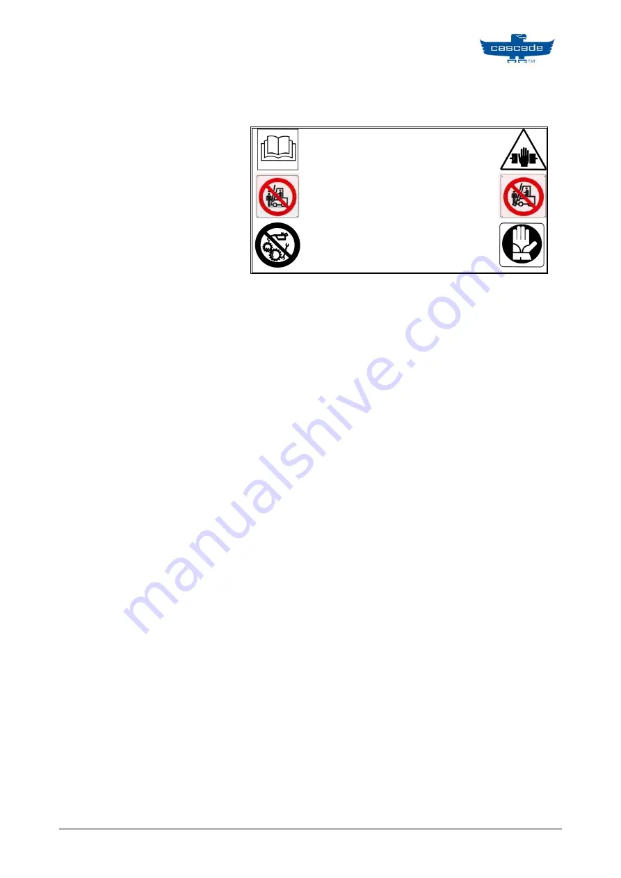
The horizontal gripping device is fitted with the pictogram shown 
below, which bears the main safety warnings and precautions that 
should be observed for machine use. 

Read the warnings and instructions for use 

carefully before using the machine or 

performing maintenance operations.  

It is strictly forbidden to stand underneath 

the forks, to stand on top of them and to 

stand in the lift truck’s range of action.  

It is absolutely forbidden to clean, oil, 

grease, repair or adjust parts with the 

machine in movement. 

Hazard  of  crushing  between  the  truck’s  front  structure  and
that of the lifting set when completely tilted backwards.

Hazard  of  shearing  between  the  truck’s  front  structure  and
that  of  the  parts  that  move  vertically  with  the  lifting  set
completely tilted backwards.

Hazard of shearing between the fixed frame and the device’s
moving arms.

Hazard of crushing between:

o

The  chains  and  the  relative  pulleys  and  the  transversal
connections of the uprights themselves.

o

Between the fixed frame and the device’s moving arms.

Hazard of crushing during arm dismantling and replacement
phases.

Hazard  of  crushing  during  cylinder  dismantling  and
replacement phases.

Hazard  of  crushing  during  installation  and  maintenance
operations.

Summary of Contents for UTF2-08-1004-1885315

Page 1: ...r rt t N Nu um mb be er r C Ca at ta al lo og g n nu um mb be er r S Se er ri ia al l n nu um mb be er r ORIGINAL INSTRUCTIONS Via dell Artigianato 1 37050 Vago di Lavagno VR ITALIA Tel 39 045 8989111 Fax 39 045 8989160 www cascorp com UTF UTF2 08 1004 1885315 UTF2 08 1004 1885315 ...

Page 2: ...EMBLY Error Bookmark not defined 3 1 11 CONTROL BOX ASSEMBLY Error Bookmark not defined CONTROL BOX ASSEMBLY Error Bookmark not defined 4 GENERAL SAFETY REGULATIONS 17 4 1 SAFETY PLATES AND PICTOGRAMS 18 4 2 RESIDUAL HAZARDS 18 5 OPERATIVE INSTRUCTIONs 19 5 1 DESCRIPTION OF MANOEUVRES 19 5 2 IMPORTANT RECOMMENDATIONS FOR CORRECT DEVICE INSTALLATION 19 5 2 1 PRELIMINARY INFORMATION 19 5 2 2 SCALING...

Page 3: ...so by CASCADE ITALIA S r l 1 1 1 TYPOGRAPHICAL CONVENTIONS This user manual uses the following typographical conventions Symbol Meaning NOTE The notes contain important information outside the main text and should be read carefully CAUTION Caution messages contain the procedures described in the manual that must be observed non compliance may cause damage to the device ATTENTION Attention messages...

Page 4: ... loads to manoeuvre bodies with cylindrical surfaces to manoeuvre people or animals to manoeuvre bodies gripped by the tip of the arm only manoeuvring loads when people or animals are present in the device s work area manoeuvring unstable loads manoeuvring groups of different sized cartons at the same time The purpose of horizontal gripping devices is to grip handle unload and stock boxed material...

Page 5: ...hnical features The device s technical features can be deduced from the model code printed on the EC plate Device type UEA device with pivoting arms UTB device with fixed arms UEC device with one fixed arm usually the left and a single or double pivot UED device with double pivot arm UEE device with one pivoting arm usually the left and a double pivoting arm UTB carton clamp telescopic sideshifter...

Page 6: ...6 2 2 Nameplate Legend ...

Page 7: ...7 ...

Page 8: ...I CODES 1 2 Cilindro Cylinder assy 6566052 2 2 Cilindro Cylinder assy 6552412 3 1 Gruppo Protezione Bumper 6583521 4 1 Ganascia sinistra Arm subassembly left 6583490 5 1 Ganascia destra Arm subassembly right 6583512 6 1 Impianto oleodinamico Hydraulic group 6563775 7 1 Telaio Frame group 6522766 1 2 4 5 6 7 3 ...

Page 9: ... BESCHREIBUNG CODE 1 CAPSCREW M6x16 6400227 12 2 CAPSCREW M14x70 6405055 12 3 WASHER M14 6406255 12 4 BEARING 6432009 16 5 BLOCK SLIDER 6432033 12 6 NUT 6504163 2 7 MOUNTING PLATE 6506606 1 8 MOUNTING PLATE 6506607 1 9 GUIDE BAR DUAL 6504121 2 10 SPACER 6540046 8 ...

Page 10: ...10 3 1 3 Mount Group ...

Page 11: ...11 2 3 3 Hydraulic system set Description Codes Hydraulic system set 6563775 ...

Page 12: ...ED 16 1 6533826 HOSE ASSEMBLY JIC 6 17 1 6533827 HOSE ASSEMBLY JIC 6 18 1 6533828 HOSE ASSEMBLY JIC 6 19 1 6533829 HOSE ASSEMBLY JIC 6 20 1 6533830 HOSE ASSEMBLY JIC 6 21 1 6533831 HOSE ASSEMBLY JIC 6 22 1 6533834 HOSE ASSEMBLY JIC 6 23 1 6533835 HOSE ASSEMBLY JIC 6 24 2 6533836 BRACKET 25 8 685866 LOCKWASHER M5 26 8 768202 NUT M5 27 8 768784 CAPSCREW HEX SOCKET 28 2 METRIC PLUG M12 29 6 604511 FI...

Page 13: ...N 6533441 VALVE GROUP 1 1 Contact Cascade VALVE PLUGGED 2 4 778100 FITTING M16 FLARELESS 3 1 609234 PLUG HEX SCKT 4 3 609455 PLUG HEX SOCKET HD 5 1 604510 PLUG 6 1 6038929 CART VALVE PO CHECK 7 1 6056395 RELIEF CARTRIDGE DIF SET 8 1 210266 FLOW DIVIDER COMBINER ...

Page 14: ...rs GA CL OP OP CL Attachment Valve OP CL SSL SSR 2 Port Hose Reel OR Internal Reeving 2 Port Hose Reel Truck Tank Truck Tank Truck Relief Valve Truck Relief Valve Truck Pump Solenoid Truck Pump 1 2 Two Truck Auxiliary Valves Truck Auxiliary Valve 1 SIDESHIFT 2 CLAMP OR FORK POSITION OR Internal Reeving CLAMP OR FORK POSITION and SIDESHIFT Truck Auxiliary Valve ...

Page 15: ... Description CODICE CODE 1 4 CAPSCREW 6400227 2 4 BEARING 6432009 3 4 LOCKING PLATE 6431458 4 2 WASHER 6494502 5 2 NUT 6495524 6 1 NUT 6504163 7 1 ARM BONDED LH 6583508 1 ARM BONDED RH 6583516 8 1 INTERMEDIATE ARM RIGHT 6560452 1 INTERMEDIATE ARM LEFT 6560424 ...

Page 16: ...ITEM QTY PART N DESCRIPTION 6242855 FITTING 1 2 Backrest Group 1 16 ...

Page 17: ... truck bearing loads that cannot be positioned centrally The load must be grasped by entire arm the load should rest on the load backrest of the frame and on the protection devices on the sliding rail When the truck is moving with the device but without a load keep the arms in the least open position possible or however in a position that is globally narrower than the device s frame It is forbidde...

Page 18: ...h the machine in movement Hazard of crushing between the truck s front structure and that of the lifting set when completely tilted backwards Hazard of shearing between the truck s front structure and that of the parts that move vertically with the lifting set completely tilted backwards Hazard of shearing between the fixed frame and the device s moving arms Hazard of crushing between o The chains...

Page 19: ... 3 from 2501 to 4999 500 20 40 60 150 4 from 5000 to 8000 600 45 60 80 150 5 from 8000 to 10999 600 60 80 100 150 Pressure values valid unless shown otherwise on the device s plate and EC certificate 5 2 2 Scaling the hydraulic system In addition to the pressure and hydraulic capacity values sent by the truck correct device functioning depends on the type of supply system used between the truck di...

Page 20: ... 19 8 2 7 13 5 27 0 54 0 30 2 0 10 0 20 0 40 0 4 1 20 3 40 6 81 2 40 3 3 16 6 33 2 66 4 5 4 27 0 54 0 108 0 50 4 9 24 6 49 1 98 2 7 3 36 7 73 4 146 8 60 6 8 33 8 67 5 135 0 10 1 50 5 101 0 202 0 70 8 9 44 3 88 5 177 0 13 2 66 1 132 2 264 4 ø3 8 G ø 9 5 mm approx Oil viscosity 20 Cts Oil viscosity 100 Cts L 1 m L 5 m L 10 m L 20 m L 1 m L 5 m L 10 m L 20 m 20 0 4 2 2 4 4 8 8 1 4 6 8 13 6 27 2 30 0 ...

Page 21: ...tion it is necessary to remove wrapping to remove the device s lower brackets ATTENTION all loading and manoeuvring operations made using the truck must be performed central to the centre of gravity on the fork compared to its dimension and weight distribution ...

Page 22: ...ight in order that the fork holder plate s upper cone hooks up with the device see detailed figure Line up the device s central retainer 06 with the central niche of the forkholder plate Reposition the lower brackets n 05 and tighten the screws with the torque wrench setting as shown in point 5 6 ...

Page 23: ...that there are no blow bys in hydraulic connections between the truck device Check that the device command lever moves properly Check the slider the clearances and the plate When the device is loadless perform a number of opening and closing and side shift if present cycles leaving approximately 10 seconds with the lever activated at the end of the run Check that the device s control devices confo...

Page 24: ...alia in writing will cause the invalidation of the EC mark and product guarantee Do not wash the UTB using jets of water at high pressure After each wash all the parts must be greased once more Every day check that the rod and the surface are free from damage marks or any other fault that could jeopardise correct cylinder functioning Check the condition of the tubing and joints according to the hy...

Page 25: ...ng the sliders is a routine operation that must be performed in order to guarantee correct lubrication and therefore safe and easy usage of the Horizontal Gripping Device The guides are pre lubricated in the production phase and therefore do not require lubrication when the device is installed for the first time ATTENTION lubrication operations must only be performed with truck power off ...

Page 26: ...th a brush Re assemble the arms by performing the abovementioned steps in reverse order Screw the rod partially on to the ring nut or joint Apply a film 10mm of thread for rods with diameters less than 50mm 20 mm for diameters from 50 to 80 mm and the entire thread for diameters greater than 80mm of medium mechanical resistance thread locking glue e g loctite 243 as shown in diagram Fully tighten ...

Page 27: ... connections between the cylinder buds and the device s hydraulic system Pay careful attention to oil leaks from the joints Remove the cylinder blocking nut ATTENTION switch off truck power before commencing cylinder dismantling and reassembling operations Pay careful attention to oil leaks from tubing and joints on cylinder Place a container beneath to receive any leaks NOTE before replacing the ...

Page 28: ...ix the nut with medium mechanical resistance thread locking glue e g loctite 243 Reassemble the hydraulic connections between the cylinder buds and the device s hydraulic system Reassemble the device on the forkholder plate of the truck as described in 4 2 3 Replace the arms as described in 5 4 Reconnect the device s hydraulic connection to the truck and perform a few opening and closing cycles an...

Page 29: ...708 4 1 O ring 70 duro 643373 5 1 Rod seal 6521345 6 1 Piston wear ring 7 1 Piston 6402629 8 1 Retainer 6402610 9 1 Rod wiper 6521341 10 1 O ring 6406906 11 1 Rod seal 6407005 12 1 O ring 70 duro 6406652 13 1 Backup ring 6402648 14 1 Piston seal 6402628 SEAL KIT 6527400 Cascade Italia supply only complete Seal kit ...

Page 30: ...iption P N 1 1 Shell weldment 6566053 2 1 Rod 6566054 3 1 Spacer tube 4 1 O ring 70 duro 643373 5 1 Rod seal 6521345 6 1 Piston wear ring 7 1 Piston 6402629 8 1 Retainer 6402610 9 1 Rod wiper 6521341 10 1 O ring 6406906 11 N A 12 1 O ring 70 duro 6406652 13 1 Backup ring 6402648 14 1 Piston seal 6402628 ...

Page 31: ...skets use extractor to remove seal gasket 5 LOCTITE2701 PISTO N ROD A thin layer of BC101 grease Tecnolube or equivalent PTFE grease which an NLGI 2 consistency is applied to the gaskets and protects them if the cylinder does not work for a long time it also prevents accidental scratching during assembly Type of gasket Ref OR basket RING NUT 1 Seal basket RING NUT 2 Dust scraper basket RING NUT 3 ...

Page 32: ... various device components Type of coupling Type of product to be used at room temperature Sliding of arm sliders on sliding rail SHELL SUPER GREASE AM or equivalent lithium based grease with an NLGI 2 consistency ATTENTION different products may only be mixed if sure of absolute compatibility ...

Page 33: ... hydraulic system The Clamp is slow in opening and closing movements and grip is insufficient 3 1 The relief valve is under calibrated compared to requirements Tighten valve enough to hold the load Calibrate checking the temperature using a full scale 250 bar pressure gauge introduced in the place of plug M Careful attention should be paid not to tighten the valve beyond the calibration of the tru...

Page 34: ...y dla Maszyn Dyrektywa 2006 42 EEC uaktualnionej oraz państwowymi przepisami uzupełniającymi corresponde a las exigencias básicas de la directiva de la CE sobre máquinas directiva CE 2006 42 CEE incluidas las modificaciones de la misma y la correspondiente transposición a la ley nacional este în conformitate cu dispozițiile Directivei mașinii Directiva 2006 42 EEC astfel cum a fost modificată prec...

Reviews: